Static- and Electronic-Trip Units
Static-trip devices are completely static; that is, there are no moving parts. These devices use semiconductor-integrated circuits, capacitors, transformers, and other electric components. Static-trip devices operate to open the circuit breaker when the current–time relationship exceeds a preselected value. The energy required to trip the breaker is obtained from the circuit being protected. No external power, such as DC batteries, is required. The complete static-trip system is comprised of (1) primary circuit current transformers,
(1) the static logic box, and (3) the tripping actuator (a magnetically held latch device).
The current transformer sensors are of toroidal type mounted one per phase on the primary studs of the circuit breaker. These transformers pro- vide a signal to the static-trip device proportional to the primary current.
The static logic box receives the signal from the primary current transformer. It monitors the signal, senses overloads or faults, and executes the required action in accordance with preselected settings. The tripping actuator receives the output signal from the static logic box and in turn causes the circuit breaker contacts to open.
Manufacturers have made great strides in the development and application of solid-state trip devices over the past 10 years or so. The motivation for this effort has been to bring protective devices to market that offer improved features over the original direct-acting designs yet preserve the totally self- contained concept exhibited by their forerunners. When the static trips were first introduced, manufacturers struggled to provide reliable and repeatable devices that would prove to be lower maintenance items than the ones they replaced. Their difficulties were not easy to overcome. The main problem has always been related to a consistent and accurate method to both derive operational power from the signals resulting from current flowing through the breaker, and to accurately measure the current at the same time. The developments came one by one. For some time, most manufacturers still had to rely on a magnetic device to get an INST function. The designs of that time did not allow an electronic device to build up sufficient power to trip the actuator fast enough to be called INST.
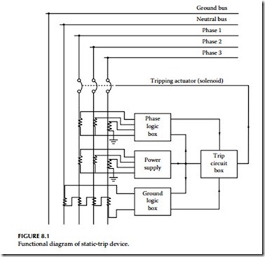
Some designs have used (and may still use) two sets of current sensors, or one set of sensors with dual secondary windings, in order to derive a signal to monitor and another to act as the power supply. Additional sensors may be required for a function that direct-acting trips could not offer— ground fault. Both three-phase, three-wire; and three-phase, four-wire ground fault detection systems are offered. The signals from either the three or four sensors are processed to determine if all INST currents add up to zero (Kirchoff’s current law applied to three-phase AC systems). Therefore, it should be apparent that if grounding conductors are used, they should not be included along with any neutral connections. When current returns to its source via a ground conductor, the monitored currents no longer add up to zero and the trip device activates. The connections and current sensors used for a three-phase, four-wire, plus ground conductor on a feeder breaker are shown in Figure 8.1.
Advances and enhancements are continually being made on static and elec- tronic-trip devices. For example, the older type static- and electronic-trip ele- ments measured peak and/or average currents and then scaled these currents to rms values based on the properties of pure sine wave. Therefore, the older static- and electronic-trip elements along with the electromechanical analog- type trip elements are susceptible to tripping problems due to harmonic cur- rents generated by nonlinear loads. The nonlinear loads are variable speed drives, switch-mode power supplies, electronic ballasts, and the like. The cur- rent electronic units are truly microprocessor based and are programmed to sample the current waveform at required intervals to calculate the effective rms value of the load currents. Microprocessor trip elements with rms sens- ing avoid false tripping problems due to harmonic current peaks and sense
the true heating current in the circuit. In addition, microprocessor trip elements provide the capability for digital readouts of voltage, currents, kilo- watts, kilowatt demands, kilowatt hours, kilovars, power factor, frequency, and so on. These readouts can be local or can be interfaced to a remote loca- tion via digital communication network. Some microprocessor protection packages can provide additional protection features that were originally available only by means of installing additional protective relays.
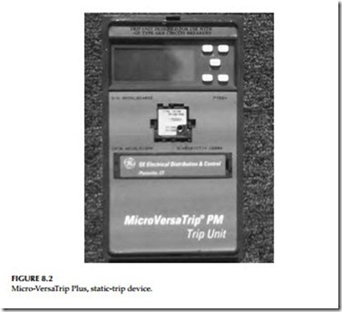
Also, the current microprocessor trip elements have less energy require- ments for static-trip logic. In general, most designs now use fewer and smaller current sensors than would have been supplied for the breaker whose sche- matic is shown in Figure 8.1. A good example of a modern static-trip device is the Micro-VersaTrip, RMS-9 Programmer (MVT) offered by General Electric distribution and control which is shown in Figure 8.2. Not only does this device offer all of the features mentioned above but also it has the ability to measure the true rms current. This makes the breaker immune to false trip- ping due to current waveforms with high distortion or harmonic content. The MVT system consists of the following parts.
Three current sensors are mounted on the breaker and provide the self-powered input to the protection programmer. Where four-wire ground fault is specified, a fourth current sensor is mounted near the neutral bar in the cable compartment. Sensors are constructed of molded epoxy for added protection against damage and moisture. Optional current sensors with four taps are available to increase the flexibility and range of the system. In the current designs rating plug is provided for a given sensor and breaker to establish the continuous current carrying capability (rating) of the breaker.
A flux-shift device is automatically powered and controlled by the protection programmer and causes the breaker to trip on command. This low-energy positive action tripping device is located near the trip bar on the breaker. This device automatically resets when the moving contacts on the breaker have fully opened.
The protection programmer has a programmable microelectronic proces- sor with laser-trimmed custom-integrated chips that form the basis of the flexible, precise MVT protection system. MVT protection programmers may be furnished with
• Up to nine adjustable time–current functions
• Three local and remote mechanical fault indicators
• Local and remote long-time pickup light emiting diode (LED) indicator
• Zone selective interlocking
• Integral ground-fault trip
All adjustable programmer functions are automatic and self-contained and require no external relaying, power supply, or accessories.
Monitoring and Protection Packages
A natural outgrowth of the move to static-trip devices has been to provide devices that can display the quantities they are monitoring. This trend has come in response to user’s concerns regarding the convenience in monitoring loads and in troubleshooting a given distribution system. Low-voltage switchgear generally has space constraints within its breaker cubicles; consequently, mount- ing space (if any) for additional current transformers is limited. Manufacturers are beginning to offer monitoring packages that take advantage of the signals already made available by the protection devices. The information can be dis- played on the trip device or sent to a cubicle door mounted display. Automated data processing centers and cogeneration sites have set up elaborate monitoring systems by taking advantage of the communications functions that are now offered. Almost every feeder at a user’s site can be monitored and all of its electri- cal performance data sent back to a central system. The trend in interfacing this basic electrical monitoring with communications to field programming units (FPUs); remote terminal units (RTUs), programmable controllers (PLCs) used as sequence controllers, data collectors, or concentrators; and sequence control and data acquisition (SCADA) systems is expected to continue. Many of the elements used in these systems are now installed directly in the switchgear.

