Block casting
Carefully examine the fire deck for pulled head bolt threads, eroded coolant pas- sages, missing or damaged coolant deflectors, and cracks, particularly between adja- cent cylinders. In some cases, minor cracks can be ground out and filled. Several dimensional checks also need to be made at this time.
Deck flatness
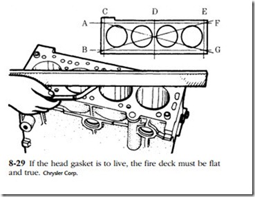
Figure 8-29 illustrates the basic technique, which involves a series of diagonal and transverse measurements along the length and width of the deck, using a machinist’s straightedge and feeler gauge. Block deck surfaces can he milled flat (a process called decking), although contemporary design practices give little leeway for corrective machining. As mentioned in Chap. 7, several modern engines cannot be safely decked, and warped blocks must be replaced. However, when it comes to it, most machinists will push these limits and obtain piston-to-cylinder head clearance by shimming the gasket or by selective assembly, fitting the shortest piston and rod sets that can be found. The owner should be aware of these expedients and agree to them.
Piston height
While this is an assembly dimension, an early check is not out of order. Measure piston protrusion or regression with a dial indicator, as described in the previous chapter.
Liner height
A few engines continue to be built with integral cylinder bores, machined directly into the block metal or in the form of a sleeve permanently installed during the casting process. These engines have fiat decks, and what will be said here does not apply.
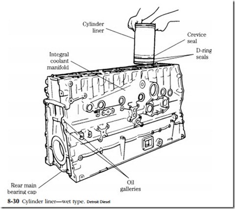
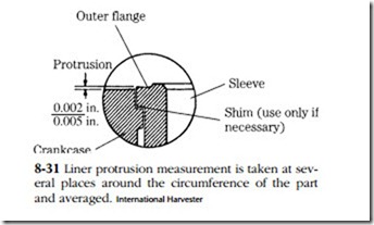
Most diesel engines employ discrete cylinder bore liners, or sleeves, which can be more or less easily replaced. Dry liners press into block counterbores; wet liners insert with a light force fit and come into direct contact with the coolant. Seals con- fine the coolant to areas adjacent to ring travel (Fig. 8-30). Wet liners simplify foundry work and give better control of water-jacket dimensions. The interface between dry liners and cylinder bores erects a minor, but real, thermal barrier between combus- tion and coolant. However, the liner is a structural member and eliminates the possibility of coolant leaks into the crankcase or back into the combustion chamber. Liners of either type stand proud of the deck, a practice that gives additional compression to the head gasket in a critical area and, at the same time prestresses the liner (Fig. 8-31). Any liner that does not meet specification must be replaced.
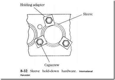
This measurement taken at several points around the circumference of the liner, should be made during initial teardown and after replacement liners are installed. Figure 8-32 illustrates the liner hold-down hardware used in machine shops. Clamps are normally fabricated on site from cold-rolled steel, fitted with hardened washers, and pulled down securely. This technique works for dry liners and wet liners with radial (O-ring type) seals. Liner counterbores—the ledges that establish liner height—can be remachined and shimmed when necessary. The more usual procedure is to shim the liner shoulder, as shown in the illustration.
Some wet liners fit so loosely that seal resiliency can affect liner height when the cylinder head is removed. John Deere and other manufacturers that use this type of liner provide detailed loading instructions. Neither do engines fitted with these liners
tolerate moving the crankshaft with the head detached. If this is done, piston-ring friction will raise the liners and possibly damage the O-ring seals.
Boring
Ascertain the amount of bore wear. Most wear occurs near the top of the cylinder at the extreme end of ring travel. This wear is caused by local oil starvation and
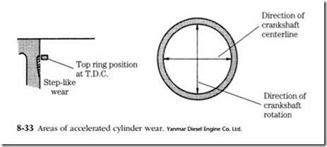
combustion-related acids. Pronounced wear, sometimes taking the form of scuffing, can occur at right angles to the crankshaft centerline on the bore surface that absorbs piston angular thrust. An engine that turns clockwise when viewed from the front will show more wear on the right side of its cylinders than on the left. In addition, axial thrust forces can generate wear in bore areas adjacent to the crankshaft cen- terline (Fig. 8-33). These forces account for most of the taper and eccentricity exhib- ited by worn cylinders. Block distortion accounts for the rest.
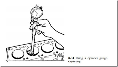
Some idea of bore condition can be had by inserting a ring into the cylinder with the flat of a piston. The difference in ring end gap between the upper and lower por- tions of the cylinder, as determined with a feeler gauge, roughly corresponds to cylinder wear. However, such techniques do not substitute for repeated and aver- aged measurements with a cylinder bore gauge (Fig. 8-34).
Study the surface of the bore under a strong light. Deep vertical scratches usu- ally indicate that the air filter has at one time failed. The causes of more serious
damage—erosion from contact with fuel spray, galling from lack of lubrication, rips and tears from ring, ring land, or wrist pin lock failure—will be painfully obvious.
Integral or dry-sleeve bores can be overbored and fitted with correspondingly oversized pistons. When the bore limit is reached, replacement sleeves can be fitted to either type, although the work is considerably easier on an engine that was orig- inally sleeved.
The common practice is to use a boring bar for the initial cuts and finish to size with a hone, preferably an automatic, self-lubricating hone such as the Sunnen CV. The finish will approximate that achieved by the original equipment manufacturer (OEM).
The accuracy of the job can only be as good as the datum—the reference point from which all dimensions, including the bore-to-crankshaft relationship, are taken. Most boring bars index to the deck, on the assumption that the deck is parallel to the main bearing centerline. This is a large assumption. The better tools index to the main bearing saddles. The cylinder with most wear is bored first; how much metal must be removed to clean up this cylinder determines the bore oversize for the engine.
Oversized piston and ring assemblies are normally supplied in increments of 0.010 in. (or 0.25 mm) to the overbore limit. A few manufacturers offer 0.05 in. over pis- tons for slightly worn cylinders. Occasionally one runs across a 0.015-in. piston and ring set.
The overbore limit varies with sleeve thickness, cylinder spacing (too much overbore compromises the head gasket in the critical “bridge” area between cylinders), and the thickness of the water jacket for engines with integral bores. Jacket thickness depends, in great part, on the quality control exercised by the foundry. Some blocks and whole families of engines have fairly uniform jacket thickness; others are subject to core shift and the unwary machinist can strike water. A final consideration, not of real concern unless the engine is really “hogged out” beyond continence, is obtaining a matching head gasket. The gasket must not be allowed to overhang the bore.
Of course, it is always possible to replace dry liners and to install liners in worn integral bores. The latter operation can be expensive, and most operators would be advised to invest in another block.
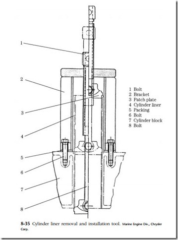
Dry sleeves are, by definition, difficult to move; wet sleeves can also stick and some have more propensity for this than others. In short, liner removal and installation tools must be used. Figure 8-35 illustrates a typical combination tool. This or a similar tool must be used for extraction, but a press and a stepped pilot—one diameter matching
liner inner diameter (ID), the other, liner outer diameter (OD)—is the better choice for installation.
Liner bores and counterbores (the ledge upon which the liner seats) require careful measurement and inspection. Out-of-spec counterbores can sometimes be machined and restored to height with shims, Cumming’s fashion.
Wet-liner seals must be lubricated just prior to installation to control swelling. Seal contact areas on the water-jacket ID should be cleaned and inspected under a light. Some machinists oil dry sleeves; others argue against the practice.
Some sleeves, wet or dry, tend to crack at the counterbore area after a few hours of operation. The most common causes have to do with chamfers, either the chamfer on the counterbore or the chamfer on the liner installation pilot.
Detroit Diesel reboring
These two-cycle engines require some special instruction. Many Series 71 engines are cast in aluminum. Early production inserts were a slip fit in the counter- bore; current standards call for the liner to be pressed in. In any event, the block should be heated to between 160° and 180°F in a water tank. Immerse the block for at least 20 minutes.
Counterbore misalignment can affect any engine, although mechanics generally believe that the aluminum block is particularly susceptible to it. You will be able to detect misalignment by the presence of bright areas on the outside circumference of the old liner. The marks will be in pairs—one on the upper half of the liner and the other diagonally across from it, on the lower half. The counterbore should be miked to check for taper and out-of-roundness.
Small imperfections—but not misalignment between the upper and lower deck—can be cleaned up with a hone. Otherwise, the counterbore will have to be machined. Torque the main-bearing caps. Oversize liners are available from the OEM and from outside suppliers such as Sealed Power Corporation.
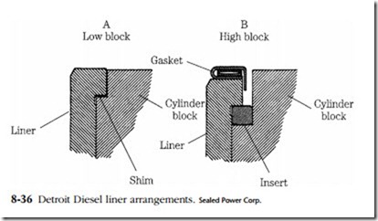
Liners on early engines projected 0.002–0.006 in. above the block (Fig. 8-36). These low-block engines used a conventional head gasket and shims under the liner
to obtain flange projection. Late-model high-block engines use an insert below the liner. Narrower-than-stock inserts are available to compensate for metal removed from the fire deck, and in various oversized diameters to accommodate larger liners. A 0.002-in. shim is also available for installation under the insert.
Note: Inserts can become damaged in service and can contribute to upper liner breakage.
Series-53 engines employ a wet liner. The upper portion of the liner is sur- rounded by coolant and sealed with red silicone seals in grooves on the block. Early engines had seals at the top and above the ports. Late-model engines dispense with the lower seal. A second groove is machined at the top of the cylinder to be used in the event of damage to the original.
The seals must be lubricated to allow the liners to pass over them. Do not pre- soak the seals, because silicone expands when saturated with most lubricants. The swelling tendency is pronounced if petroleum products are used. Lubricate just prior to assembly with silicone spray, animal fat, green soap, or hydraulic brake fluid. Carefully lower the liners into the counterbores, without twisting the seals or dis- placing them from their grooves.
The eccentricity (out-of-roundness and taper) must be measured before final assembly. On the 110 series you are allowed 0.0015 in. eccentricity. The 53 and 71 engines will tolerate 0.002 in. Eccentricity can often be corrected by removing the liners and rotating them 90° in the counterbores. Do not move the inserts in this operation.
Honing
Honing is used to bring rebored cylinders to size and to remove small imperfections and glaze in used cylinders. Glaze is the hard surface layer of compacted iron crystals formed by the rubbing action of the rings. Most engine manufacturers recommend that the glaze be broken to add in ring seating and to remove the ridge that forms at the upper limit of ring travel. The Perfect Circle people suggest that honing can be skipped if the cylinder is in good shape.
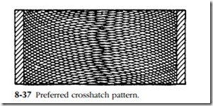
The pattern should be diamond-shaped, as shown in Fig. 8-37, with a 22-32 intersection degree at the horizontal centerline. The cut should be uniform in both directions, without torn or folded metal, leaving a surface free of burnish and imbedded stone particles. These requirements are relatively easy to meet if you have access to an automatic honing machine. However, satisfactory work can be done with a fixed- adjustment hone turned by a drill press or portable drill motor.
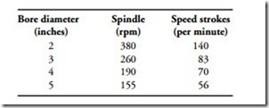
The hone must be parallel to the bore axis. Liners can he held in scrap cylin- der blocks or in wood jigs. The spindle speed must be kept low—a requirement that makes it impossible to use a 1/4 in. utility drill motor. Suggested speeds are shown below.
Move the hone up and down the bore in smooth oscillations. Do not let the tool pause at the end of the stroke, but reverse it rapidly. Excessive pressure will load the stone with fragments, dulling it and scratching the bore. Flood the stones with an approved lubricant (such as mineral oil), which meets specification 45 SUV at 100°F.
Stone choice is in part determined by the ring material. Most engines respond best to 220–280 grit silicon carbide with code J or K hardness.
Cleaning the bore is a chore that is seldom done correctly. Never use a sol- vent on a honed bore. The solvent will float the silicon carbide particles into the iron, where they will remain. Instead, use hot water and detergent. Scrub the bore until the suds remain white. Then rinse and wipe dry with paper towels. The bore can be considered “sanitary” when there is no discoloration of the towel. Oil immediately.
Piston rings
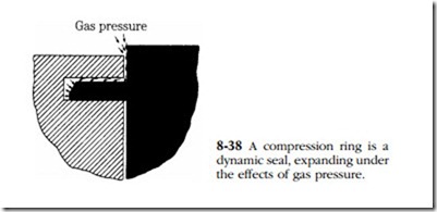
Piston rings are primarily seals to prevent compression, combustion, and exhaust gases from entering the crankcase. The principle employed is a kind of mechanical jujitsu—pressure above the ring is conducted behind it to spread the ring open against the cylinder wall. The greater the pressure above the ring, the more tightly the ring wedges against the wall (Fig. 8-38).
The rings also lubricate the cylinder walls. The oil control ring distributes a film of oil over the walls, providing piston and ring lubrication. One or more scraper
rings control the thickness of the film, reducing chamber deposits and oil consumption. In addition to sealing and lubrication, the ring belt is the main heat path from the piston to the relatively cool cylinder.
Rings are almost always cast iron, although steel rings are used in some extreme-pressure situations. Cast iron is one of the very few metals that tolerate rubbing contact with the same material. Until a few years ago rings were finished as cast.
Today almost all compression rings are flashed with a light (0.004 in.) coating of chrome. Besides being extremely hard and thus giving good wear resistance, chrome develops a pattern of microscopic cracks in service. These cracks, typically accounting for 2% of the ring’s surface, serve as oil reservoirs and help to prevent scuffing. A newer development is to fill, or channel, the upper compression ring with molybdenum. The outer diameter of the ring is grooved and the moly sprayed on with a hot-plasma or other bonding process. Besides having a very low coefficient of friction and a very high melting temperature, moly gives a piston ring surface that is 15–30% void. It retains more oil than chrome-faced rings and is, at least in theory, more resistant to scuffing.
Rings traditionally have been divided into three types, according to function. Counting from the top of the piston, the first and second rings are compression rings, whose task is to control blowby. The middle ring is the scraper, which keeps excess oil from the combustion space. The last ring is the oil ring, which is serrated to deliver oil to the bore.
This rather neat classification has become increasingly ambiguous with the development of multipurpose ring profiles and the consequent reduction in the number of rings fitted to a piston. Five- and six-ring pistons have given way to three- and four-ring pistons on many of the smaller engines. The function of the middle rings is split between gas sealing and oil control. The lower rings, while primarily operating as cylinder oilers, have some gas-seating responsibilities. Design has become quite subtle, and it is difficult for the uninitiated to distinguish between com- pression and scraper rings.
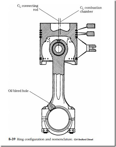
The drawing in Fig. 8-39 illustrates the ring profiles used on the current series of GM Bedford engines. Note the differences in profile among the three. These pro- files are typical, but by no means, universal. The Sealed Power Corporation offers several hundred in stock and will produce others on special order.
What this means to the mechanic is that he or she must be very careful when installing rings. Most have a definite up and down, which might or might not be indicated on the ring. Usually the top side is stamped with some special letter code. Great care must be exercised not to install the rings in the wrong sequence. New rings are packaged in individual containers or in groups that are clearly marked 1 (for first compression), 2, and so forth. Reusable rings should be taken off the piston and placed on a board in the assembly sequence.
Ring wear
The first sign of ring wear is excessive oil consumption, signaled by blue smoke. But before you blame the rings, you should check the bearing clearances at the main
and crankpin journals. Bearings worn to twice normal clearance will throw off five times the normal quantity of oil on the cylinder walls. You can make a direct evalu- ation of oil spill by pressurizing the lubrication system. If appreciable amounts of oil are getting by the rings, the carbon pattern on the piston will be chipped and washed at the edges of the crown.
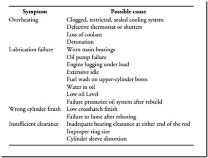
Check the rings for sticking in their grooves (this can be done on two-cycles from the air box), breaks, and scuffing. The latter is by far the most common malady, and results from tiny fusion welds between the ring material and cylinder walls. Basically it can be traced to lack of lubrication, but the exact cause might require the deductive talents of a Sherlock Holmes. Engineers at Sealed Power suggest these possibilities
Usually inadequate bearing clearance, complicated by a poor fit in the block counterbore, results in overheating. The fundamental cause is often poor torque procedures, or improperly installed sealing rings on wet-sleeved engines. A rolled or twisted sealing ring can distort the sleeve.
Ring breakage is due to abnormal loading or localized stresses. It can be traced to
• Ring sticking—this overstresses the free end of the ring.
• Detonation—this is traceable to the overly liberal use of starting fluid, to dribbling injectors and to out-of-time delivery.
• Overstressing the ring on installation. Usually the ring breaks directly across from the gap.
• Excessively worn grooves, which allow the ring to flex and flutter.
• Ring hitting the ridge at the top of the bore. The mechanic is at fault because this ridge should have been removed.
The last point—involving blame—can be sticky in a shop situation. Mechanics make mistakes the same as everyone else, and the number of mistakes is in part, a function of the complexity of the repair. Few people can overhaul a machine as complicated as a multicylinder engine without making some small error. Assessing blame, if only to correct the situation, is sometimes complicated by having the mechanic who built the engine tear it down. But careful examination of the parts usually points to the fault. For example, rings that have been fitted upside down show reversed wear patterns. Rings that have broken in service are worn on either side of the break, from contact with the cylinder walls. The fracture will be dulled. Ring that have been broken during removal show sharp crystalline breaks without local wear spots.
