Selection of Grounding System
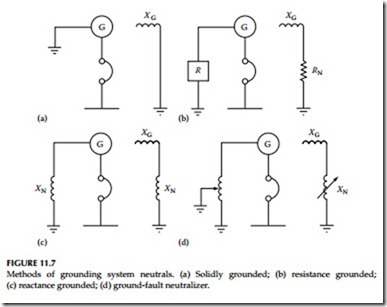
As discussed earlier, the various methods of grounding commonly used are solidly grounded, resistance grounded, reactance grounded, and ground- fault neutralizer grounded. The ungrounded system, in the true sense of the word, is grounded, because the charging capacitance from the phase conduc- tor to earth acts as the grounding point. The various grounding methods are shown in Figure 11.7.
The selection of a grounding system should be based upon the following systems factors:
• Magnitude of the fault current
• Transient overvoltage
• Lightning protection
• Application of protective devices for selective ground fault protection
• Types of load served, such as motors, generators, etc.
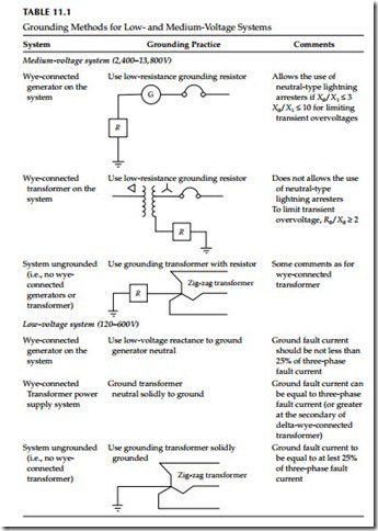
The application limits and a guide for the various grounding methods for consideration of the above-mentioned factors are shown in Table 11.1 and discussed in the following sections.
Solidly Grounded System
A solidly grounded system is one in which a generator, transformer, or grounding transformer neutral is directly grounded to earth or station ground.
Because the reactance of source (generator or transformer) impedance is in series with the neutral circuit, this system cannot be considered a zero impedance circuit. In nearly all grounded systems, it is desirable to have the line to ground fault current in the range of 25%–110% of three-phase fault current in order to prevent the development of high transient over- voltage. The higher the ground fault current, the less are the transient overvoltages.
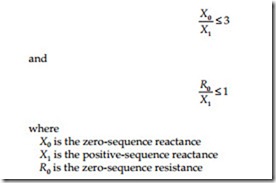
Ground-neutral-type lightning arresters may be applied on this system provided that the ground fault current is at least 60% of three-phase fault current. Another way of expressing this value is to express the reactance and resistance ratios as follows:
Normally, direct grounding of the generator is not desirable because the ground fault current may exceed three-phase fault current. Since the generator is rated for maximum three-phase fault current, it is not desir- able to have higher ground fault currents than three-phase fault current. Therefore, most grounded systems having generators are grounded through low reactance values to keep ground fault currents less than three- phase fault current. Generally, low-voltage systems (i.e., below 600 V) are solidly grounded. Medium-voltage systems may be either solidly or low resistance grounded.
Low-Resistance Grounding
In low-resistance grounding, the neutral is grounded through a resistance of low ohmic value. The reasons for using the resistance grounding system are the following:
• To reduce the ground fault current to prevent damage to switchgear, motors, cables, and the like
• To minimize magnetic and mechanical stresses
• To minimize stray ground fault currents for personnel safety
• To reduce the momentary line-voltage dips by clearing of ground faults
The line-to-ground voltage that may exist during fault conditions can be as high as the voltage present on ungrounded systems. However, the transient overvoltages are not so high. If the system is properly grounded by resistance, there is no danger from destructive overtransient voltages.
High-Resistance Grounding
In this system, the neutral is grounded through a resistance of high ohmic value. The line-to-ground voltage of unfaulted phases during a ground fault is nearly equal to line-to-line voltage. If the insulation system was selected for a grounded system, it will be subjected to an overvoltage condition during a line-to-ground fault.
The ground fault current available in this type of system is very small, usually 25 A or less. It should be remembered that when using this system the ground fault current should never be less than the charging current. Moreover, the lightning arresters for this system should be the ungrounded type. This type of system is subject to the following types of overvoltage conditions:
• Ferroresonance type, that is, resonance effects of series inductive– capacitive circuits
• Limited transient overvoltage conditions
• Overvoltage conditions due to direct connection to higher voltages
The reasons for using high-resistance grounding are similar to those for low-resistance grounding except that in this system ground fault current is limited to a very small value.
Reactance Grounding
In a reactance grounded system, the neutral circuit is grounded through a reactor. In general, reactance grounding is used for grounding generator neutrals. The value of the reactor chosen is usually such that the ground fault current is not less than 25% of three-phase fault current to prevent serious transient overvoltages during ground fault clearance. The value of X0 must be less than or equal to 10 times the X1 value for this type of system.
Ground-Fault Neutralizers (Resonant Grounded)
In this system, a reactor having a specially selected high value of reactance is connected in neutral connection to ground. The current that flows through the reactor, during a line-to-ground fault condition, is equal to and 180° out of phase with the charging current that flows in two unfaulted phases. Under this condition, the two currents cancel, leaving the faulted current due only to resistance. Because resistive current is in phase with the voltage, the fault current is quenched when both the voltage and fault current pass through zero axis.
A precaution required in this system is that care must be taken to keep the ground-fault neutralizer tuned to the system capacitance. If any switching is done to take circuits out, the neutralizer reactance values must be changed by adjusting neutralizer taps. Ground-fault neutralizers have been used only to a limited extent and are not as common as the other systems of grounding.


