Conventional Scenario in Active Power Control
The frequency of the system is dependent on active power balance and any mismatch between load and generation will be reflected into the system with changing the frequency [4]. The control of generated power and frequency in large-scale power systems is commonly referred as load–frequency control (LFC).
Primary Active Power/Frequency Control
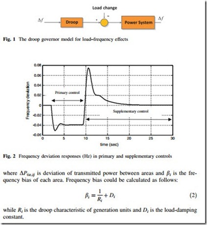
As frequency is a common factor throughout the system, a change in active power demand at one point is reflected throughout the system (Fig. 1). This issue is mainly related with LFC concept.
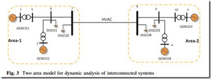
Primary frequency control is a very well-known concept in power system studies [4–8]. As shown in Fig. 2, the first reaction of speed governors of generation units will be reflected to primary control or load frequency control. At this stage, the system will try to stabilize load change and contingencies. As shown in this figure, later by applying secondary supplementary frequency control the steady state error of frequency will be covered to the desired values [6].
Supplementary Higher Level Control
In addition to primary control, another higher level control which is known as AGC will be applied to ensure the area absorbs its own load change and also to maintain net interchanges and frequency at their schedule values.
Area Control Error
The area control error (ACE) will present the imbalance of generated power and load demands within the control area. By means of ACE, any power/frequency mismatched though the interconnected system will be checked. ACE could be a linear combination of frequency deviation and net interchange [7, 8].
Area Participation Factor
Area participation factor (APF) is another important signal for doing the AGC though the supplementary control. In fact, if there will be more than one generation unit in one area or if some generation unit cannot participate in AGC, there is a possibility to manage their participation by means of participation factor. In each area, the sum of participation factors is equal to 1 [7].
Control of Interconnected Multi-Area Systems
Automatic generation control is one of the main functions of Energy Management Systems (EMS) and controlling of frequency, generated power, and transmitted power through the transmission lines are the most important responsibilities of AGC in multiarea interconnected power system.
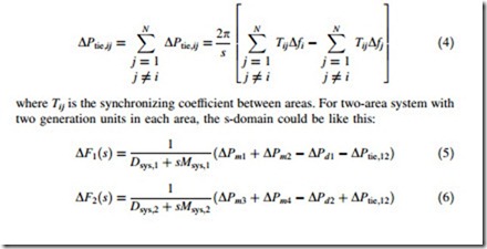
A typical system for this type of analysis is a modified two-area interconnected system [4] as shown in Fig. 3. Two generation companies (GENCO) and two distribution companies (DISCO) as loads have been considered for each area.
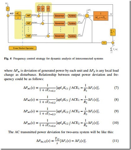
A proper control strategy for active power/frequency issue is shown in Fig. 4. A low-order linearized model could be used for modeling the load-generation dynamics. The relationships between power deviations and frequency deviation are as follows [4]:
where DPm is generated power deviation, DPL is load change, H is the inertia constant of the system (Msys = 2H) in second and D is the load damping coefficient. For modeling the interconnections between N areas, the tie-line power change between area i and the rest of area could be presented as [7, 8]:
2.3 Multi Machine Four-Area Power System Example
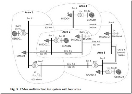
In order to show the performance of AGC in a multimachine system, a general scenario for detailed model of 12-bus test system (Fig. 5) is performed in Simpower/ MATLAB software. Complete data and parameters of this 12-bus benchmark are
given in appendix of this chapter. As explained before, the steady state error in frequency and transmitted power could not be solved by primary local frequency control. So another type of higher level control based on AGC should be implemented. Based on the defined standard for frequency regulation, the response of this higher level control will be slower than those local controllers, so AGC will be completed after starting the actions of primary frequency controllers.
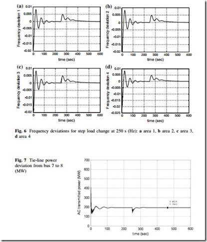
The system responses for this example are presented in Figs. 6, 7, and 8. In order to check the performance of AGC control strategy, it is assumed that after 250 s a large step load reduction around 7 % p.u. is happened for demanded load of DICSO3.1 in third area. As shown in Figs. 6 and 7, by decreasing the demanded load, the frequency start to increase, while by acting of AGC both frequency and scheduled transmitted power could remain on their scheduled values.
Usually, with using this supplementary control action in AGC strategy, perturbation in any area should be responded with the nearest units, mainly with all the units in the same area and some in the neighbors. As shown in Fig. 8, load iation in area 3 is responded with GENCO3 in the same area by decreasing its output.
