Fuses
The fuse element is a cheap, useful and simple protective device. Unfortunately, it provides protection by destroying itself. After operation a fuse must be replaced, and this requires the correct replacement fuse, the use of tools, and expenditure of time. A particular fuse can never be tested without its self destruction, and the results of the test will not necessarily apply to the replacement fuse.
A fuse is the weak link in a circuit which will break when too much current flows. It protects the circuit conductors and equipment from damage. This action is referred to as the blowing, breaking or rupturing of the fuse. It must be remembered that the priority of the fuse is to protect the circuit conductors, not the appliance. Calculation of cable size therefore automatically involves the correct selection of protective devices. There are many different types, shapes and sizes of fuse available. All are designed to perform specific functions.
The fuse depends on the heating effect of an electric current for its operation. An overcurrent in the circuit results in the thermal melting of the fuse link or fuse element.
The fuse element consists of a wire of defined current carrying capacity placed in series with the circuit being protected. It will carry its rated current without overheating. When excess current flows the fuse element overheats, melts and disconnects the circuit from the supply. The term fuse refers to the whole device. The following are important terms associated with fuses.
· Rated Voltage A fuse must be suitable for the voltage at which it is going to be used. The selected fuse should have a voltage rating equal to, or greater than the circuit voltage.
· Rated Current The maximum current a fuse will carry indefinitely without undue deterioration of the fuse element.
· Fusing Current The minimum current required to ‘blow’ the fuse.
· Fusing Factor The ratio between the fusing current and the rated current which is expressed as follows: Fusing Factor = Fusing Current divided by Rated Current. Fusing factor is usually between 1.4 and 2 and its significance is illustrated by the following example.
Example: A 20 Amp fuse with a fusing factor of 1.4 will carry 20 Amps continuously and will blow when a current of 20 x 1.4 Amps, i.e 28 Amps flows.
· Breaking Capacity or ( Rupturing Capacity ) When a fuse element breaks, it is essential that the resulting arc does not cause mechanical damage to the fuse carrier or base. The fuse must therefore be capable of safely interrupting the greatest possible short-circuit current that may occur. ( Prospective Short Circuit Current )
The Cartridge Fuse
This the most common type of fuse used in this country.
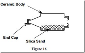
Figure 16 illustrates a DZII cartridge fuse which consists of a ceramic body having two tinned brass end caps. It is filled with silica sand, and its ceramic body is both heat proof and an electrical insulator.
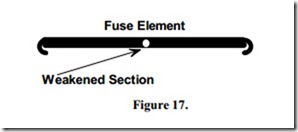
Figure 17 illustrates the fuse element, located inside the fuse, which carries the current required by the load on the circuit. When an excessive current flows, the element overheats and ruptures or breaks. As the element breaks, an arc occurs. Current tends to keep flowing through this arc. The silica sand extinguishes the arc and so the circuit is opened or disconnected.
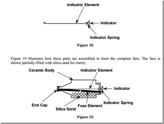
Figure 18 illustrates the indicator element which is a very thin section of fuse wire. It ruptures at the same time as the fuse element. When this occurs the small spring ejects the indicator and gives a visual indication that the fuse has ruptured or “blown”.
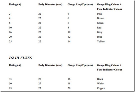
The DZII fuse is available in the following current ratings: 2 A, 4 A, 6 A, 10 A, 16 A, 20 A and 25 A.
For ratings above 25 A, a physically larger fuse known as the DZIII fuse is used. DZIII fuses are now banned by the ETCI Rules as they have a record of overheating. However, DZIII fuses are still available for replacement purposes in current ratings of 35 A, 50 A and 63 A.
The indicator on DZ type fuses is colour coded, to enable the fuse size to be determined without having to withdraw the fuse. The opposite end, referred to as the tip, is tapered to a different dimension for each current rating.
A gauge ring of the correct size must be installed in the fuseholder, prior to installing the fuse. A gauge ring is a device which is designed to prevent a higher rated fuse being installed when a fuse has to be replaced. Gauge rings are manufactured to match the tip size and indicator colour of the DZ fuse. The following chart indicates these colours and approximate fuse tip and gauge ring sizes.
A DZII fuse may be inserted into a DZIII fuse unit with the use of a ceramic fuse liner. The fuse liner centres the DZII fuse in the DZIII fuse-holder.
All DZ fuses must have the supply connected to the fuse tip for safety reasons. A gauge ring must always be used, otherwise good contact cannot be guaranteed.
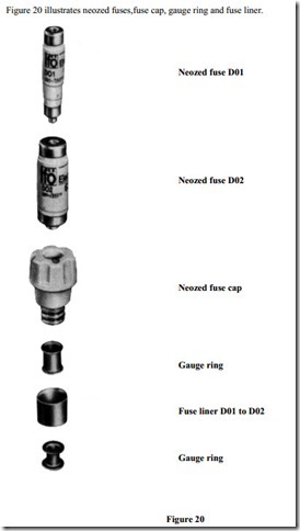
The DZII fuse has been replaced by a more compact and reliable fuse known as the NEOZED fuse. The Neozed fuse is available in three physical sizes covering the range 2 A to 100 A as follows:
 The type of main fuse normally used in a domestic installation is the D02. It is usually rated at 63 A. Some larger domestic installations require a D03, rated at 80 A or 100 A. There is a range of adaptor sleeves available to prevent a higher rated fuse being installed accidentlly. The fuse indicators are colour coded the same as the DZII and DZIII types.
Using manufacturers time / current charts it is possible to determine how long it will take a particular fuse to “blow”, when carrying a given value of overload current.
N.B. These fuses can safely interrupt an overload current up to 80 kA. ( 80,000 Amps ).
This in other words is its breaking capacity.
