TIME DOMAIN
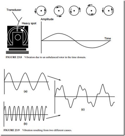
Figure 23.8 shows vibration due to an unbalanced rotor in the time domain. The amplitude of vibration is proportional to the amount of imbalance, and the cycle repeats itself once per revolution. Analysis in the time domain becomes more difficult when there is more than one vibration component present.
Figure 23.9 illustrates a situation where two sine wave frequencies are present. The individual components of this combination are difficult to derive from a time domain display.
The impulsive signal from bearings and gear defects can be detected in the time domain. It is also useful for analyzing the phase relationships of the vibration signals. However, it is difficult to determine the individual components of complex signals. The frequency domain is used to analyze these components.

