Magnetic Clutches
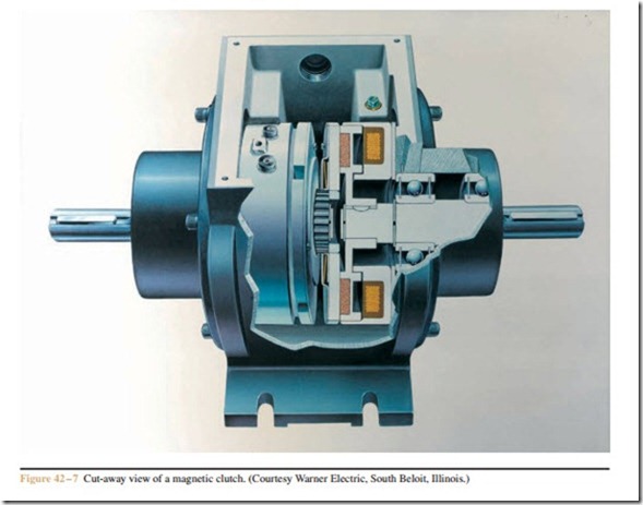
Magnetic clutches are used in applications where it is desirable to permit a motor to reach full speed before load is applied. Clutches can provide a smooth start for loads that can be damaged by sudden starting, or for high inertia loads such as centrifuges or flywheels. Magnetic clutches are divided into two primary sections: the field section, which contains the slip rings and coil winding; and the armature section, which contains the clutch disc (Figure 42–6). When power is applied to the field winding through the slip rings and brushes, the armature is attracted to the field, coupling the motor to the load. The force of coupling can be con- trolled by adjusting the voltage supplied to the field. This permits control over the degree of slip between the field section and the armature section. The amount of slip will determine how rapidly the motor can accelerate the driven load and the amount of initial torque de- livered to the load. When power is removed from the clutch, a spring separates the field and armature. A magnetic clutch is shown in Figure 42–7.
The clutch illustrated in Figure 42–6 is a single face clutch, which means that it contains only one clutch disc. Clutches intended to connect large horse- power motors to heavy loads often contain multiple clutch faces. Double faced clutches have both the ar- mature and field discs mounted on the same hub. A double faced friction lining is sandwiched between
them. When the field winding is energized, the field disc and armature disc are drawn together with the double faced friction lining between them. Double faced clutches can be obtained in sizes up to 78 inches in diameter.
Some clutches are intended to provide tension control and are operated with a large amount of slip- page between the driving and driven members. These clutches produce an excessive amount of heat because of the friction between clutch discs. Many of these clutches are water cooled to help remove the heat.
