VARIABLE-FREQUENCY INVERTERS
Inherently, ac motors are not as well suited to variable-speed applications as are
dc motors, because their speed cannot be satisfactorily controlled by simple supplyvoltage
variation. Reducing the supply voltage to a 60-Hz three-phase induction
motor will reduce its speed all right, but it also drastically worsens the motor’s
speed-regulating ability. That is, an ac induction motor operating at reduced voltage
is unable to maintain a reasonably steady shaft speed in the face of slight changes
in torque demand imposed by the mechanical load.
Satisfactory speed control of an ac induction motor can be accomplished only
by varying the supply frequency while simultaneously varying the supply voltage.
If the source of power is the 60-Hz ac utility line, frequency variation is a much
more difficult task than voltage variation. Nevertheless, we are sometimes willing
to take the trouble to build a variable-frequency drive circuit for controlling the
speed of an ac motor, so that we can take advantage of certain intrinsic superior
characteristics of ac machines. These intrinsic superiorities of ac induction motors
over dc motors are:
1. An ac induction motor has no commutator or friction-slip type electrical
connections of any kind. It is therefore easier to manufacture and less expensive
than a dc machine. With no brushes to wear down, its maintenance
costs arc lower.
2. Because it has no mechanical commutator, an ac motor produces no sparks;
it is therefore safer.
3. With no electrical connections exposed to the atmosphere, an ac motor holds
up better in the presence of corrosive gases.
4. An ac motor tends to be smaller and lighter than a comparable-power dc
motor.
There are two basic methods of producing a variable-frequency, high-power,
three-phase source for adjusting the speed of an industrial ac induction motor. The
two methods are;
1. Convert a dc source into three-phase ac by firing a bank of SCRs in a certain
sequence at a certain rate. A circuit which does this is called an inverter.
2. Convert a 6()-Hz three-phase ac source into a lower-frequency three-phase
ac source, again by firing banks of SCRs in a certain sequence at a certain
rate. A circuit which does this is called a cycloconverter.
We’ll deal with inverters now and take on cycloconverters in Sec. 15-10.
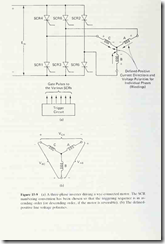
Figure 15-9(a) is a schematic diagram of a three-phase inverter driving a wyeconnected
induction motor. The SCR gate-triggering circuits are not shown since
we are concentrating on the action of the SCRs’ main terminals at this time. We
want to understand how turning the SCRs ON and OFF in the proper sequence
causes the dc supply to be switched across stator windings* A, B, and C of the
motor in such a way that a rotating magnetic field is created, thus duplicating the
action of a three-phase ac source.
To understand how this happens, it is necessary to refer to the schematic
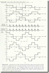
diagram of Fig. 15-9(a), the stator winding current and voltage waveforms (the top
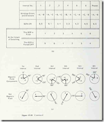
three waveforms) of Fig. 15-10(a), the SCR switching sequence of Fig. 15-10(b),
and the magnetic field vector diagrams of Fig. 15-10(c).
Because of the physical placement of stator winding A , it produces a magnetic
field component oriented from the 60° mechanical position, when current is flowing
*Stator windings .4. B. and C of a three-phase machine are often referred to as pluises A. B,
and C. In this conte.vt, we will use the terms suilor windiiif; and phiisc interehangeahly.
through it in the defined-positive direction.* If current flows through winding A
in the negative direction, its magnetic field component reorients by 180 mechanical
degrees, coming from the 240° position. (Visualize a compass rose.)
Similarly for stator windings B and C. Positive current through B produces
a field component from 180°, and negative current through B gives a field component
from 0°. For winding C, positive current gives a field component from 300°
and negative current gives a field component from 120°, since 300° — 180° = 120°.
The cyclical operation of the SCR bridge circuit in Fig. 15-9(a) is divided into
six equal-duration time intervals. Let us define our first time interval to be that
time when the electronic triggering circuitry causes SCRs 6 and 5 to be turned ON,
and all other SCRs to be turned OFF. This state of affairs is indicated by the first
column of Fig. 15-10(b). Never mind how the triggering circuitry causes this; we’ll
consider that topic later.
With SCRs 6 and 5 turned ON. there is a current flow path as follows: from
the + dc supply terminal, through SCR6, through stator winding A in the positive
direction, through stator winding B in the negative direction, through SCR3, and
down the dc supply line to the – dc supply terminal. No current exists in stator
winding C at this time because SCRs 4 and 1 are both OFF.
The top three waveforms of Fig. 15- 10(a) show these stator winding currents
graphically. During the first time interval, the A winding current (and voltage) is
positive, the B winding current is negative, and the C winding current is zero.
These winding currents produce magnetic field components oriented as shown in
the 1st time interval of Fig. 15-10(c). The net magnetic field F resulting from these
components is oriented from the 30° mechanical position on the stator, as the figure
indicates.
At the end of the first time interval, the triggering circuitry fires SCRl and
forces SCR5 to turn OFF. These events are tabulated at the bottom of Fig. 1,5-
10(b). The new combination of turned-ON SCRs is the 6-1 combination. Therefore
throughout the second time interval the motor winding currents are positive through
phase A, negative through phase C, and zero in phase B. Trace out the current
flow path on Fig. 15-9(a) to verify this for yourself. The waveform graphs of Fig.
15-10(a) illustrate these current conditions during the second time interval.
In Fig. 15-10(c) the magnetic field components are seen to come from 60°
due to the +A current, and from 120° due to the -C current; these components
combine to produce a net field from the 90° mechanical position on the stator.
Thus, the switching of the SCRs as we proceeded from the first to the second time
interval has produced a 60° rotation of the net stator field (from the 30° position
to the 90° position).
At the end of the second time interval the triggering circuit fires SCR2 and
forces OFF SCR6, leaving SCRs 2 and 1 ON. The winding currents are positive
*A11 motor phases have defined-positive current directions as indicated in Fig l.’>-y(u), with
current flowing from the outside supply line toward the wye tic-point. Since a motor winding is an
electrical load, each one has its defined-positive voltage polarity as + on the current-entry end, and
– on the current-exit end, as that figure shows.
through Band negative through C during the third time interval. This is documented
in Fig. 15-10(b) and graphed in Fig. 15-l(Xa)- You can trace out the current path
in Fig. 15-9(a). The new magnetic field components resulting from these winding
currents cause another 60° rotation in the net stator field, to the 150° position, as
shown in Fig. 15-10(c).
As this process continues through the fourth, fifth, and sixth time intervals,
the SCRs are triggered ON and forced OFF in accordance with the schedule listed
in Fig. 15-I0(b). That sequence of SCR combinations produces the stator winding
current waveforms drawn in Fig. 15-10(a), which cause the net stator magnetic
field to keep advancing in 60-degree jumps. In this way the rotating field effect of
a three-phase ac line is reproduced.
The motor torque is not instantaneously constant as it would be if the motor
were driven by a three-phase sine-wave source. But neither is it as abrupt as the
Fig. 15-10(a) waveforms might suggest, since the inductance of the motor windings
tends to smooth out the steep edges of the current waveforms.
Stand back and get an overall view of the A. B. and C waveforms in Fig. 15-
10(a). If each time interval is regarded as a 60° portion of the complete operating
cycle, then these three waveforms are all out of phase from one another by 120°,
like three-phase sine-wave ac. This is a consequence of the manner in which the
triggering/turn-OFF circuit has handled the SCRs—allowing an individual SCR to
remain conducting for 120° (two time intervals), but changing the combining SCR
halfway through the 120° conduction angle.
The line-to-line voltages V,,^. Vbc and Vca are also 120° phase-displaced from
one another, as the three waveforms at the bottom of Fig. 15-10(a) make clear.
Also note that the line voUages lead the phase vohages by 30°, just the same as
for sine-wave three-phase ac.
The line voltage waveforms can be derived by subtracting one phase waveform
from another phase waveform. For example, Vj^g is derived by subtracting the Vp
waveform from the K4 waveform; as always, subtraction is equivalent to signinversion
and addition. Thus, during the first time interval, the instantaneous value
of V^g is obtained by changing the sign of the instantaneous value of Vg (which is
-Ell), yielding + E/2, then adding that to the instantaneous value of V^ ( + E/2).
The result is + E/2 + E/2 = + E. which agrees with the 1st interval of the V^g
waveform. Every other interval of every line voltage can be derived in the same
manner.
Of course, the whole appeal of the inverter is that its waveform frequency is
variable. The frequency is determined by the rate at which the trigger/turn-OFF
circuit delivers gate pulses to the six SCRs. The time between gate pulses always
corresponds to 60° of the waveform cycle. If the gate pulses are spaced closer
together in time, then 60° becomes a shorter time, a full cycle takes a shorter time,
the frequency rises, and the motor speeds up. Conversely, if the gate pulses are
spread further apart in time, the motor slows down.
The motor’s direction of rotation can be reversed by altering the gate pulse
sequence, again through the medium of the trigger/turn-OFF circuit. If we changed
the trigger/turn-OFF circuit so that the SCR bridge worked its way through the
schedule of Fig. 15-l(J(b) from right to left, instead of from left to right, the motor
would reverse direction.
In a dc-supplied circuit, getting an SCR to turn ON is no problem; it’s getting
it to turn OFF that’s the problem. Naturally, an inverter must contend with this
problem. Many different circuit arrangements have been devised for forcing an
SCR to turn OFF {forced commutation, as opposed to natural commutation). One
popular method, mentioned in Sec. 4-7, is to use a solid-state switching device to
connect a charged capacitor across an ON SCR so that the capacitor voltage temporarily
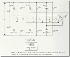
reverse-biases the main terminals of the SCR. Such a scheme is illustrated
in Fig. 15-11, in which the solid-state switching devices are smaller “auxiliary”
SCRs. They are labeled with the letters AUX to clearly distinguish them from the
main SCRs that actually carry the load current. Here is how they work.
If any main SCR is ON, the stator winding that it controls has a voltage of
magnitude £/2 developed across it. This voltage charges the associated commutating
capacitor through associated resistor R, always with the proper polarity for reversebiasing
the conducting SCR. When the associated auxiliary SCR is gated ON, the
charged commutating capacitor forces the main SCR to turn OFF.
For example, suppose we are presently in the 1st time interval of Fig. 15-
10(b). Negative current is flowing through phase B of the motor, developing a
voltage across that phase which is -I- at the inside wye tie-point and — at the
outside line. This voltage appears across the Rg-C^ series combination, causing Cg
to charge -I- on the right and — on the left. At the end of the 1st time interval,
the trigger/turn-OFF circuit sends a gate pulse to AUX5 at virtually the same instant
that it sends a gate pulse to SCRl. These gate pulses are shown just below the
three winding current waveform graphs in Fig. 15-10(a). When AUX5 turns ON,
it acts like a short circuit connecting the right ( + ) side of Cg to the cathode of
SCR5. The left ( — ) side of Cg is wired directly to the anode of SCR5. The resulting
reverse bias across SCR5 persists until Cg can discharge through R^ and winding
B, which is long enough to force SCRS OFF.
Now consider that we are in the 4th time interval of Fig. 15-10(b). SCR2 is
ON, carrying positive current through winding B. The voltage across winding B
charges Cg -I- on the left and – on the right. At the end of the fourth time interval
a gate pulse is sent to AUX2; see the gate waveforms in Fig. 15-10{a). This causes
Cg to be connected in parallel with SCR2, with the positive (left) side of Cg on
the cathode and the negative side on the anode. Here again Cg succeeds in commutating
OFF the main SCR that was passing current through winding B.
In the same manner, commutating capacitor C^ forces OFF SCRs 6 and 3
at the proper moments, through the action of AUX6 and AUX3, respectively;
and C( forces OFF SCRs 4 and 1 at the proper moments through AUX 4 and
AUX 1.
Usually in capacitor-based forced-commutation circuits it is desirable to maintain
the reverse bias across the SCR’s main terminals for only a short time, just
long enough to remove the charge carriers that have accumulated near the internal
junctions of the SCR, thereby reducing the current to less than the hold-ON value
If^Q. For medium- and high-current SCRs, the time required to do this is generally
less than 100 /<s.
The arrangement in Fig. 13-11 allows a commutating capacitor to maintain
reverse bias until it discharges through its associated series resistor and motor
winding. Because the series resistance value must be fairly high in order to isolate
the three commutating circuits from one another, the capacitor discharge time
constant tends to be fairly long, considerably longer than 100 ,«s. So there is a
conflict between the necessity of isolating the commutating circuits and the desirability
of removing the commutation voltage from the SCR quickly. This conflict
is often resolved by the installation of discharge diodes in parallel with the main
SCRs, to provide a low-resistance discharge path. The placements of discharge
diodes D4 and Dl, associated with SCR4 and SCRl, are indicated by the dashedline
connections at the far left in Fig. 15-11. As that circuit schematic makes clear,
the diode installation establishes a low-resistance path back around to the auxiliary
SCR, by which the commiitating capacitor can discharge quickly. Discharge diodes
6, 3, 2 and 5 would be placed across their associated SCRs in the same manner.
Concerning the design of the trigger/turn-OFF circuit in Fig. 15-11, there are
several methods that can be employed to generate the sequence of gate pulses
graphed in Fig. 15-10{a). One approach is to use the sequential switching circuit
of Fig. 5-7, extended to six stages. Load 1 would be a pulse transformer with a
dual secondary, one winding driving the gate of SCRl in Fig. 15-11 [delivering
pulse gMl in Fig. 15-lU(a)], and the other winding driving the gate of AUX5
[delivering pulse gX5 in Fig. 15-10(a)]. Load 2 in Fig. 5-7 would be a pulse transformer
supplying simultaneous gate pulses to SCR2 and AUX6 in Fig. 15-11 [pulses
gM2 and gX6 in Fig. 15-lU(a)], and so on.
By ganging together all of the l-Mfi adjustment pots in Fig. 5-7, the pulse
intervals would be made uniform and adjustable, providing the inverter with its
variable frequency capability.
An alternative method of generating the gate pulse sequence is by microprocessor.
To terminate the 1st time interval, the //P program writes a 1 to a
particular bit in an output port, from which the HI signal is appropriately processed
to produce the gMl and gX5 gate pulses. The program then jumps to a delay
subroutine to wait until the end of the second time interval. At the proper moment
in real time, the /<P returns from its delay subroutine to the main program, where
it encounters an instruction to write a 1 to a different bit of the output port. The
HI signal on this bit would be hard-wired to SCR2 and AUX6 (after appropriate
processing). In this way the gate pulses gM2 and gX6 are delivered to the inverter,
causing it to switch out of the conditions for the second time interval and into the
conditions for the third time interval. The program then jumps back into the delay
subroutine to spend the same amount of time as before, waiting for the end of the
third time interval. And so on.
Variable-frequency control is attained by altering the amount of time the
program spends in the delay subroutine. This can be done by writing the subroutine
so that its duration depends on the contents of a particular RAM location, and
then using the //P”s monitor program to vary that RAM value.
To achieve closed-loop motor speed control, the user-program itself would
be designed to make the necessary alterations to the delay subroutine in order to
automatically adjust the inverter’s output frequency. The user-program would make
any time-delay alteration in response to the error signal it calculates by subtracting
the set-point speed from the actual measured motor speed.


