MAIN COMPONENTS OF A POWER TRANSFORMER
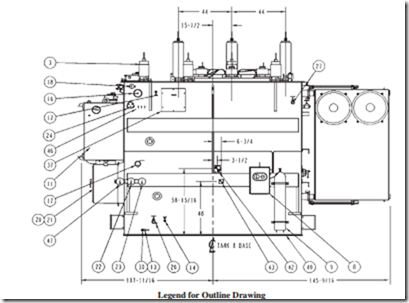
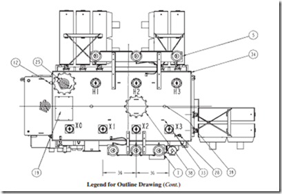
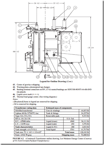
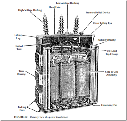
Figure 4.2 illustrates the outline drawing of a transformer. Figure 4.3 illustrates a cutaway view of an oil-filled transformer. The main components of the transformer are as follows:
1. Concrete base. This is to provide support for the transformer. It must be leveled and fire-resistant.
2. Core. It provides a route for the magnetic flux and supports the low-voltage and high- voltage windings.
3. Low-voltage winding. It has fewer turns compared with the high-voltage windings. Its conductor has a large diameter because it carries more current.
1. 3 H. V. bushings; 69 kV, 350 kV B.I.L. 400 amps, C/W 1.50″-12 silver-plated stud. 2″ usable thread length. LAPP Cat #B-88726-70. Internal bushing lead is drawlead connected. Shipping weight per bush- ing is 139 lb.
2. 3 L. V. bushings; 25 kV, 150 kV B.I.L. 2000 amps, C/W 1.50″-12 silver-plated stud. 2.5″ usable thread length. LAPP Cat # B-88723-70. Internal lead is bottom connected.
3. 1 L. V. neutral bushings; 25 kV, 150 kV B.I.L. 2000 amps, C/W 1.50″-12 silver-plated stud. 2.5″ usable thread length. LAPP Cat # B-88723-70. Internal lead is bottom connected.
4. 3 H. V. lightning arresters, 60 kV, 48 kV MCOV. Ohio brass polymer housed, station class PVN 314048-3001. Shipping weight of arrester is 53.6 lb.
5. H. V. lightning arrester supports C/W seismic bracing. Shipping weight of supports is 304 lb.
6. 3 L. V. lightning arresters, 9 kV, 7.65 kV MCOV. Ohio brass polymer housed, station class PVN 314008-3001. Shipping weight of arrester is 21.3 lb.
7. L. V. lightning arrester supports C/W seismic bracing. Shipping weight of supports is 138 lb.
8. Nitrogen preservation system, ABB Type RNB, in a hinged, lockable door compartment C/W regula- tors, cylinder pressure gauge, empty cylinder alarm switch, transformer tank pressure/vacuum gauge, high- & low-tank-pressure alarm switches & tank gas space sampling valve. Connected to a nitrogen cylinder.
9. Nitrogen cylinder.
10. Deenergized tap changer handle C/W position indicator & provision for padlocking.
11. Load tap changer, Reinhausen Type RMV-II, C/W Qualitrol Self-Sealing Pressure Relief Device #208-60U, C/W deflector, alarm contacts & semaphore, liquid level indicator C/W contacts, 11⁄2″ NPT drain valve with sampler, dehydrating breather, vacuum interrupters and monitoring system. (See wiring diagram.)
12. 2 – 1″ globe valves located approximately 6′ below cover.
13. Ground connectors, Anderson # SW11-025-B.
14. 1″ globe valve and plug.
15. 2 – Multiaxis impact recorders (one at each end). To be returned to Ferranti-Packard.
16. Magnetic liquid level indicator C/W contacts. (See wiring diagram.)
FIGURE 4.2 Transformer outline drawing, Los Medanos Energy Center (Courtesy of VA Tech Ferranti- Packard Transformers.)
17. Rapid pressure rise relay C/W contacts. Located under oil. (See wiring diagram.)
18. Pressure vacuum gauge C/W bleeder.
19. C. T. outlet box for current transformer leads continued to control cabinet.
20. Weatherproof control cabinet C/W LTC motor drive and C/W 7″ 211⁄4 ” opening(s) in bottom.
21. Nameplate.
22. Liquid temperature indicator C/W contacts. (See wiring diagram.)
23. Winding temperature indicator C/W Contacts. (See wiring diagram.)
24. Thermowell for liquid temperature indicator and winding temperature indicator.
25. Qualitrol Self-Sealing Pressure Relief Device #208-60U C/W deflector, alarm contacts & semaphore. (See wiring diagram.)
26. 2″ NPT globe valve for draining C/W sampler.
27. 2″ NPT top filter press globe valve.
28. 2″NPT globe valve located on tank cover for vacuum filling.
29. 2″ NPT globe valve (for F.P. Use).
30. Copper-faced ground pads.
31. 4 – Transformer lifting lugs, each C/W a 21⁄2 ” dia. hole. Use slings with minimum leg length of 12 ft.
32. 4 – Transformer jacking steps.
33. Cover lifting lugs.
34. Tank cover (welded on).
35. 7 Detachable cooling radiators C/W shutoff valves, lifting lugs, 1″ NPT top vent C/W brass plug and 1″ NPT bottom drain plug. Shipping weight per radiator is 1336 lb.
36. 9 Cooling fans C/W guards, 2 stages. (See wiring diagram.) Shipping weight per fan is 35 lb.
37. Accessible core ground(s), inside box C/W 5-kV bushings.
38. 2 – 18″ dia. manholes.
39. Safety harness anchor rod (for F.P. use).
40. Slab base suitable for skidding and rolling in both directions.
41. 2 sets of seismic radiator bracing per radiator bank (1 at top & 1 at bottom). Shipping weight per set is 41 lb.)
42. Center of gravity—operation.
FIGURE 4.2 (Continued) Transformer outline drawing, Los Medanos Energy Center (Courtesy of VA Tech Ferranti-Packard Transformers.)
4. High-voltage winding. It has a larger number of turns, and its conductor has a smaller diameter than the low-voltage winding conductor. The high-voltage winding is usually wound around the low-voltage winding (only cooling ducts and insulation separate the windings). This is done to minimize the voltage stress on the core insulation.
5. Tank. It houses the windings, core, and oil. It must be strong enough to withstand the gas pressures and electromagnetic forces that could develop when a fault occurs.
6. Oil. It is a good-quality mineral oil. It provides insulation between the windings, core, and transformer tank. It also removes the heat generated. The oil is specially refined, and it must be free from impurities such as water, inorganic acid, alkali, sulfur, and vegetable and mineral oil.
Note: Some transformers use Askarel, which is nonflammable insulating and cooling medium, instead of insulating oil. It gives good fire protection, which is a significant advantage when the transformer is located inside a building. However, Askarel contains polychlorinated biphenals (PCBs). They have been linked to cancer-causing sub
stances. Therefore, they have been banned. Most industries are now in the process of replacing transformers containing Askarel with dry-type transformers or transformers containing mineral oil.
7. Thermometer. It measures the oil temperature and initiates an alarm when the temperature exceeds the alarm set point.
8. Low/high-voltage bushing. This ceramic bushing carries the low/high-voltage conduc- tor and insulates it from the tank. The high-voltage bushing is usually filled with oil to enhance the heat removal capability.
9. Low/High-voltage connection. It connects the low/high-voltage conductor to the circuit.
10. Conservator tank. It contains oil and has the capability of absorbing the swell of the oil when it becomes hot.
11. Gas detector relay. Electrical faults are characterized by the formation of gas. In the early stages of the fault, small quantities of gas are liberated. The amount of gas formed increases with time, and a violent explosion could occur. Most of the damage and expense can be saved if the fault can be discovered and corrected in its early stages. The gas detector relay detects gas buildup in the tank. Any gas generation inside the transformer passes through it. It has two parts. One part detects large rate of gas pro- duction which could be caused by a major fault (such as hydrogen, acetylene, and car- bon monoxide). The second part detects the slow accumulation of air and gases which are released from the oil when it gets warm or from minor arcs. When the gas level reaches a predetermined amount, an alarm is annunciated. The relay has also the capa- bility to trip the transformer in case of a serious fault which would result in a sudden rush of oil or gas through it.
12. Explosion vent. It prevents the buildup of high pressure in the tank due to gas forma- tion (caused by oil disintegration) when a fault occurs. A relief diaphragm at the end of the explosion vent ruptures when the gas pressure reaches a certain predetermined value, to relieve the pressure to atmosphere.
13. Oil level. The oil level changes with the temperature of the oil. The core and winding must always be immersed in oil to ensure they are adequately cooled and insulated.
14. Sight glass. It indicates oil level.
15. Breather. This allows air movement to the conservator upon swell and shrinkage of the oil. It has a silica gel (air dryer) to remove moisture from the air entering the conser- vator tank. The transformer oil must be kept dry always. A water content of 8 parts per million (ppm) in the oil will reduce the dielectric strength to a dangerous level. Oxygen has also adverse consequences on the oil (it oxidizes it, resulting in the formation of sludge). Some transformers have a seal of inert gas (nitrogen) between the oil and atmosphere to prevent oxygen and moisture from reaching the oil.
16. Radiator. It is a heat exchanger which cools the oil by natural circulation.
17. Ground connection. The tank is connected to ground (earth) to ensure the safety of maintenance personnel.
Transformer Core
The core is made from thousands of laminations of grain-oriented steel. The thickness of a lamination is around 12 mils. Each lamination is coated with a thin layer of insulating material. The windings have a circular cross section. They are normally concentric. The lowest-voltage winding is placed next to the core to reduce the voltage stress. There is a layer of insulation between the low-voltage winding and the core. There are also oil ducts and insulating barriers between the coils. The core is grounded at one point. The ground connection is normally accessible externally for test purposes.
Windings
The windings must be able to withstand the large mechanical forces created by a short cir- cuit. The winding insulation must be able to withstand the highest operating temperature without excessive degradation. The cooling fluid must be able to flow freely through spaces between the windings to remove the heat. The windings are arranged concentrically. The highest voltage is located on the outside.
Nitrogen Demand System
Many transformers are equipped with an automatic nitrogen demand system. It regulates the pressure in the transformer during the thermal cycles of the oil (swell and shrinkage of the oil). Nitrogen is used as a buffer gas between the oil and the air. Its purpose is to keep outside air (containing water vapor) from contacting the oil. The water vapor has devastating effects on the oil. The dew point of nitrogen is less than -50°C to ensure that it is very dry. Most units have an alarm indicating low nitrogen pressure in the cylinder.
Conservator Tank with Air Cell
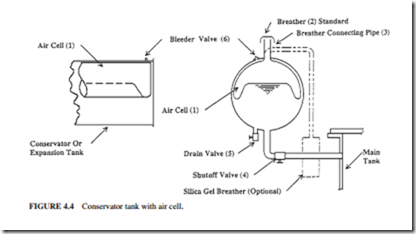
The conservator air cell preservation system is an expansion tank located above the main transformer tank. It provides a head of oil so that the transformer tank is filled always. The quality of oil in the transformer is preserved by sealing it from contaminants such as mois- ture and oxygen (Fig. 4.4).
Air is drawn into the air cell (part 1) or expelled through the breather (part 2) as the oil level changes. The air cell prevents the transformer oil from coming in direct contact with atmospheric air. The air cell will inflate and deflate as the oil volume changes in the conservator tank.
Current Transformers
Current transformers (CTs) are auxiliary transformers used normally for metering or oper- ation of auxiliary equipment and relays. They could be located inside or outside the tank assembly.
Bushings
A bushing is an insulated conductor passing through a cover of a piece of enclosed electri- cal equipment. The bushing carries the current through it and seals the opening against weather or oil pressure. It also supports the leads and provides protection against flashover due to overvoltage or heavy contamination (Fig. 4.5).
A bushing has a voltage less than 35 kV and consists of a current-carrying conductor, an epoxy or porcelain insulator, and a mechanical assembly to hold it all together. It also has terminals on the top and bottom for connection. The bushing is filled with oil for cooling.
Tap Changers
Many transformers have on-load or off-load tap changers. They change the effective number of the windings in the transformer to maintain the secondary voltage constant.
Insulation
Figure 4.6 shows the main components of a power transformer and the major uses of Kraft paper. The winding insulation is normally made of paper. Cellulose board is also used as internal insulation in liquid-filled transformers. Cellulose insulation is impregnable with the insulating fluid of the transformer. This maintains a uniform dielectric stress through- out the transformer.
Related posts:
Incoming search terms:
- draw the sectional view of a transformer
- parts of transformer
- transformer parts diagram
- Free hand sketching of transformer and auxiliary parts and sectional views
- components of transformer
- draw the sectional view of transformer
- draw the free hand sketch of transformer and sectional view
- component of transformer
- draw the free hand sketching of power transformer and auxiliary parts and sectional views
- components of a transformer
- transformer components
- auxiliary parts of transformer
- transformer main parts
- transformer parts list pdf
- main parts of transformer
- transformer parts name
- transformer and auxiliary parts and sectional views
- electrical transformer parts
- auxillary transformer test equipment mail
- draw the free hand sketching of transformer and auxiliary parts and sectional views
- transformer components and functions
- power transformer parts
- transformer parts
- parts of power transformer
- draw the free hand sketching of power transformer and auxiliary parts and sectional
- free hand sketching of transformer
- component of a transformer
- main part of transformer
- free hand sketching of power transformer and auxiliary parts and sectional views
- components of transformers
- power transformer and auxiliary parts and sectional views
- draw sectional view of transformer
- power transformer diagram
- main parts of power transformer
- transformer top view drawing
- componant of transformer
- parts of transformer pdf
- transformer and its parts
- free hand schetching of
- draw the sectinol view of a transformer
- transformer parts and functions
- 345kv transformer component diagram
- internal parts of transformer
- transformer auxiliary parts
- draw and label a transformer
- sketching of transfomer and auxiliary parts and sectional views daigram
- diagram of power transformer with auxiliary part and sectional view
- free hand sketching of tran
- pawer transformer and euxaillry parts and sectional view
- drew the transformer and auxiliary parts and secntuonal viwes
