Purely Resistive AC Circuits
Effect of Resistance in DC and AC Circuits
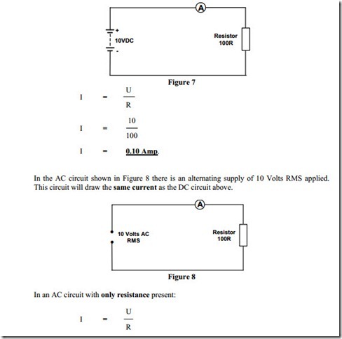
Purely resistance circuits consist of electrical devices, which contain no inductance or capacitance. Devices such as resistors, lamps ( incandescent ) and heating elements have negligible inductance or capacitance and for practical purposes can be considered to be purely resistive. For such AC circuits the same rules and laws apply as for DC circuits.
When an AC circuit contains only resistive devices, Ohms Law, Kirchoff’s Laws, and the Power Laws can be used in exactly the same way as in DC circuits.
The Effect of Capacitance in DC and AC Circuits
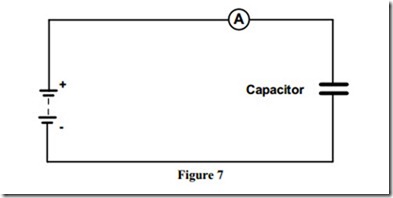
Figure 7 shows a DC supply connected to a non polarised capacitor. When the supply is switched on, the ammeter will indicate current flowing initially, and then the reading will fall off to zero. This indicates that the capacitor is charged. Because there is virtually no resistance in the circuit, the charging of the capacitor is almost instantaneous.
In a DC circuit containing only capacitance, no current flows after the initial charging current.
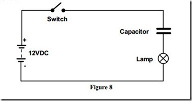
Figure 8 shows a lamp connected in series with a non-polarised capacitor across 12 V DC supply. When the switch is closed, the lamp may flicker “on” for an instant as the charging current flows through it.
This current flow reduces to zero as the capacitor charges to full capacity. At this stage the applied voltage is across the terminals of the capacitor and the voltage across the lamp has reduced to zero.
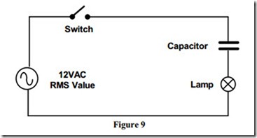
Figure 9 shows the same circuit now connected to an AC supply.
When the switch is closed, the capacitor is charged with one polarity and then it discharges; next the capacitor is charged with the opposite polarity, and then it discharges again.
The cycles of charge and discharge current provide an alternating current in the circuit, at the same frequency as the applied voltage. This is the current, which lights the lamp.
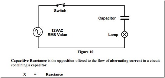
Figure 10 shows the same circuit with a lower value capacitor. This capacitor takes a lower value charge and discharge current and therefore the lamp will be dimmer. The lower value capacitor has more opposition to alternating current and so less current flows in the circuit. From this we can see that the circuit has more reactance for less capacitance.
Capacitive Reactance is measured in Ohms and is denoted in a circuit by the symbol XC.
Summary:
· When DC is applied to a circuit containing a capacitor in series with a lamp, the capacitor acts, as a blocking device and the lamp does not light.
· When AC is applied to a circuit containing a capacitor in series with a lamp, the capacitor allows current to flow through the process of charging and discharging the capacitor and as a result the lamp illuminates.
· In an AC circuit containing a capacitor, the lower the capacitance value the lower the current flow. This means that, the lower the capacitor value, the greater the opposition to current flow. This opposition is known as Capacitive Reactance ( XC ).
· A discharged capacitor behaves like a closed switch.
· A charged capacitor behaves like an open switch.
The Effect of Inductance in DC and AC Circuits
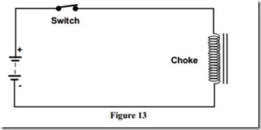
Inductance is only effective in a circuit when current is changing. The reason for this is that a changing current results in a changing magnetic field, which in turn produces a back EMF.
In a DC circuit, the effect described above occurs only when circuit current is changing.
At “Switch On” ( an increasing current causing an expanding magnetic field ) and at “Switch Off” ( a decreasing current causing a collapsing magnetic field ).
Some inductors have a very low resistance and this will result in high currents flowing when they are connected in DC circuits.
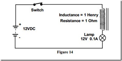
Figure 14 shows a DC supply connected to a circuit consisting of an inductor, which has an inductance value of 1 Henry and a resistance value 1 Ohm, in series with a lamp.
When the DC supply is switched on, the lamp will be bright. This indicates that the inductor has little opposition to current flow in the circuit.
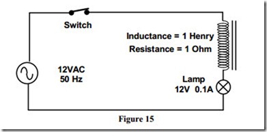
Figure 15 shows the same circuit now connected to an AC supply.
It must be remembered that an alternating current is continuously changing, i.e. the current is rising and falling. This results in a magnetic field which is continuously changing in strength and polarity. As a result of this the inductor has a continuous effect on an AC circuit.
For the circuit shown there will be a back EMF induced in the inductor, which according to Lenz’s Law opposes the supply voltage. This in turn opposes the current flow in the circuit.
The opposition to the flow of alternating current in the inductor, is called Inductive Reactance, symbol ( XL ). Inductive reactance in common with capacitive reactance and resistance is measured in Ohms. The resistance of the coil will depend on the CSA, length and type of wire used in its construction.
Although the inductor in the circuit has a resistance of 1 Ohm, it has an Inductive Reactance of 314 Ohms approximately, under the circuit conditions described. The lamp will be dim, indicating a high opposition to current flow. Contrast this with the DC circuit, dealt with previously, where the lamp was bright.
Related posts:
Incoming search terms:
- purely resistive ac circuit
- pure resistive circuit
- purely resistive circuit
- treat lamp as purely resistive
- Purely resistive means
- purely resistive ciecuit
- adding currents in a purely resistive circuit
- Purely resistive
- increasing supply frequency to a purely resistive circuit
- av power for pure resistive circuit
- application of pure resistive circuit
- whay is use pure resistive circuit
