Quadrant thyristor-controlled rectifier
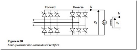
The concept of the four operating quadrants is illustrated below. It shows the four possible operating states of any drive system and shows the directions of VD and ID for the DC motor drive application. To operate in quadrants 3 and 2, it must be possible to reverse the direction of ID. This requires an additional converter bridge connected for current to flow in the opposite direction.
This type of converter is known as a four-quadrant DC converter, and is sometimes called a double or back-to-back six-pulse rectifier (Figure 6.20).
With a DC motor drive fed from a four-quadrant DC converter, the operation in all four quadrants is possible with a speed control in either the forward or reverse direction.
Operation
A change of direction of the motor can quickly be achieved. Converter-1 is used as a controlled rectifier for speed control in the forward direction of rotation, while converter- 2 is blocked, and vice versa in the reverse direction.
Assume initially, that the motor runs in the forward direction, under the control of Converter-1, with a delay angle of <90º and Converter-2 is blocked. The changeover
sequence from running in the forward direction to the reverse direction is as follows:
• Converter-1 delay angle increased to α > 90º. This means that DC voltage
VD < 0 and DC current ID is decreasing.
• When ID = 0, Converter-1 is blocked and thyristor firing is terminated.
• After a small delay, Converter-2 is unblocked and starts in the inverter mode with a firing angle greater than 90º.
• If the motor is still turning in the forward direction, converter-2 DC current ID starts to increase in the negative direction and the DC machine acts as a generator and is broken to standstill, returning energy to the supply line.
• As the firing angle is reduced to α < 90º, converter-2 changes from the inverter to the rectifier mode, and as voltage VD increases, the motor starts to rotate in the opposite direction.
In a DC motor drive, the reversal rotation direction can also be achieved by using a single converter and by changing the direction of the excitation current.
This method can only be used where there are no special drive requirements for changing over from the forward to the reverse operation. In this case, using switches in the field circuit do the changeover mechanically during a period at standstill. Considerable time delays are required during a standstill, to demagnetize the field in the reverse direction. There are many practical applications for both the uncontrolled and the controlled line-commutated rectifiers. Some of the more common applications include the following:
• DC motor drives with variable speed control
• DC supply for variable voltage-variable frequency inverters
• Slip-energy recovery converters for wound rotor induction motors
• DC excitation supply for machines
• High-voltage DC converters.
