Armature Problems
A high percentage of a DC machine’s problems occur in the commutator and brushes. Following are some of the test procedures, problems, their causes, and solutions.
Burned Commutator Bars
Burned commutator bars indicate a serious problem, and the machine will need further testing. If two spots appear at 180 electrical degrees from each other (two adjacent brush holders apart on the commutator of most armatures), the armature may have shorted coils. An armature with shorted coils should be rewound.
In some cases, the shorted coil can be cut open and the commutator segments attached to it can be shorted together. (This should be done only in an emergency.)
Dirty Commutator
The mica between the segments has to withstand low voltage, high heat, and extreme mechanical pressure. Because of the heat, this mica has no bonding or sealing agents. It has a linear grain that is flawed with voids.
Individual segments can be replaced in large commutators. In smaller commutators the whole commutator must be replaced.
This same color pattern will appear if the load stops the armature in the same spot every time. If possible, the load should be adjusted to avoid this problem.
Control and Load Problems
Any quick speed change will shorten the life of the commutator and the brushes. (Large motors must have the armature amperes reduced when starting.) A sudden speed increase will damage the commutator as much as across-the-line starting. Sudden load changes will also cause commutator damage.
In some cases, the interpoles won’t have time to react, causing the brushes to arc excessively for a short time. (Machines with a large bore have compensating windings to reduce this problem, as explained previously under “Interpoles” in Chapter 1.)
Brushes
Brushes are classified in the following groups: carbon-graphite, electrographitics, graphites, and metal graphites. Each has its own currentcarrying, wear, and filming characteristics. They can be designed for specific requirements such as low voltage/high current, dry conditions, cleaning action for overfilming, and high speed.
Brush Problems
The carbon brush used in a DC machine has a difficult job:
• It must rub on the commutator hard enough to conduct amperes.
• It has to tolerate high heat from friction, ampere flow, and arcing.
• It should cause minimal wear of the commutator material.
A properly designed brush accomplishes all of the above. Original equipment brushes don’t always work. Ambient conditions sometimes
Conduction Zone
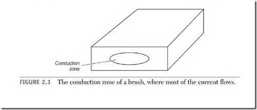
There is a small area of high current on the face of the brush called the conduction zone (Fig. 2.1). The zone current is part load current and part circulating current.
Carbon conducts better as its temperature goes up. This contributes to the current concentration in a small area. The conduction zone is roughly 10 percent of the total brush face area. (There can be more than one conduction zone on a brush face.)
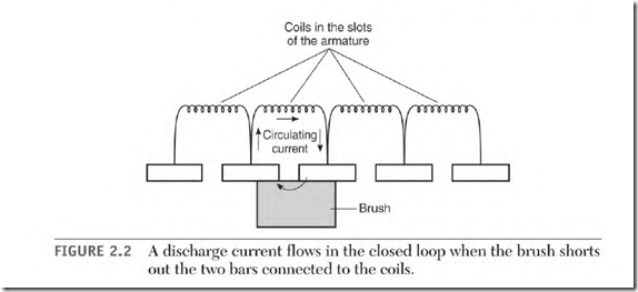
A circulating current is caused by a brush shorting two commutator segments (connected to an energized armature coil). When the brush shorts the coil’s two segments, the line current stops, and the magnetism of the coil collapses. This action creates a voltage in the coil.
The brush has joined the segments at the ends ofthe coil, creating a closed loop circuit. This circuit has low resistance, so a pulse of high current flows in it (Fig. 2.2).
The current flows in the opposite direction from what it did when the coil was part of the previous pole. It flows in the same direction as it will when the coil becomes part of the next pole.
The commutator will wear evenly if the conduction zone moves back and forth under the brush. (The zone is moving as it should if sparking at the trailing edge of the brush moves back and forth.) If it doesn’t move, or if the circulating current in the zone is too high, the commutator will be damaged.
TWO commutator bars are conducting the circulating amperes of the zone and the load amperes. If the circulating current causes excess heat, it’s
too high and must be reduced. Higher-resistance brushes will reduce the circulating current; however, they also lower the operating amperes.
Brushes that are split into two or more equal parts help control circulating current. The resistance between the brush segments lowers the circulating current without affecting the operating amperes. A split brush also enhances the movement of the conduction zone. The brush sections divide the zone area, leaving each brush section to carry only part of the zone.
Spiral Groove
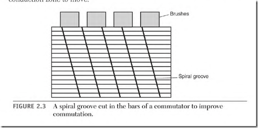
A machine is sometimes severely overloaded during its duty cycle, causing commutator damage. A spiral groove cut into the segments of the commutator (Fig. 2.3) will reduce or eliminate this damage and force the conduction zone to move.
The groove should be about twice as wide as the undercut slot of the mica, but not quite as deep. At this depth, the groove will be removed the next time the commutator is reworked on a lathe. (It’s easier to cut a new spiral than to deepen it.)
The groove should sweep across the face of a brush at least twice per revolution. Spiral grooves are common on slip rings.
Multiple Brushes
If there are multiple brushes in a brush holder, each brush must carry its share of the amperes. Brushes will wear unevenly if they are not carrying equal current.
Open frame machines can be examined with an infrared gun. Take the temperature of each brush while the machine is running. A brush that is hotter than the rest may be carrying more than its share of the amperes. A brush will arc and get hot if it doesn’t have enough spring tension.
Brush Box and Commutator Spacing
A machine’s brush boxes should be spaced at an equal distance from the commutator. The spacing should be close enough to keep the brush from chattering. This measurement can be from 1/16 inch on small machines to 1 /8 inch on large machines. (Some large machines may specify even more space.)
A piece of plastic (the right thickness) inserted between the box and commutator works well for setting the box height. Plastic or a similar material won’t scratch the commutator.
Distance Between Brushes
The distance between brushes around the commutator must be exactly the same.
Place a strip of paper (adding machine tape) under two adjacent sets of brushes. Pull the paper in the direction of the machine’s rotation so that the brushes are against the trailing side of the brush box.
Mark the paper on the trailing side of each brush set. Compare this measurement to the rest of the brushes by inserting the tape under them the same way. A difference of as little as .05 inch can affect commutation.
Brush Holder Alignment
When there are multiple brushes per holder, all brushes should contact the same segments, unless designed otherwise. Misalignment will change the number of coils per pole, causing magnetic unbalance and brush arcing.
Spring Tension
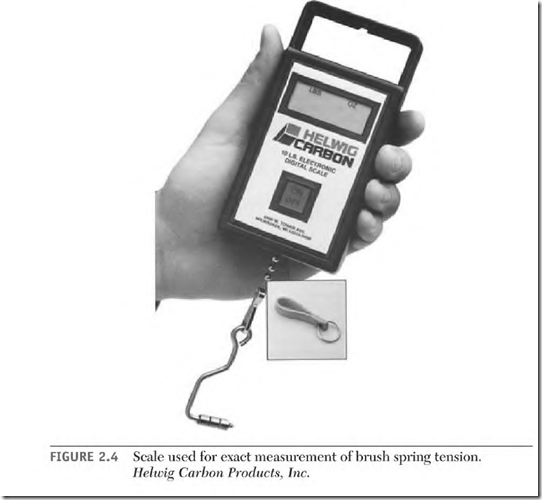
All brushes must press the commutator with the same pressure. Brushes with more spring tension will carry more amperes. A scale designed to weigh spring pressure is available from brush companies (Fig. 2.4).
The recommended spring pressure is as follows:
High-speed turbine rings and soft graphite brushes 2.25-2.75 1b
Normal speed slip rings 3.5-4.5 1b
Most industrial motors 4-5 1b
Metal graphite 4.5-5.5 1b Fractional horsepower 5-8 1b
Traction motors 5-8 1b
Angled brushes with an angle greater than 25 0 Add 1/2 1b
Brush weight must be considered when the machine has large brushes. The weight of the brush located on top is subtracted from this value, and the weight of the brush on the bottom is added to it. (The tension value of brushes located on the sides of the commutator is the same.)
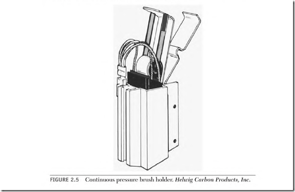
Replacing adjustable spring brush boxes with constant spring pressure brush boxes has been very successful (Fig. 2.5).
FIGURE 2.5 Continuous pressure brush holder. Heltcig Carbon Products, Inc.
Brush Shunts
The brush shunt should be well anchored in the brush and show no discoloration from heat. The shunt wire must be large enough to carry the brushes’ share of the amperes. (If the wire is discolored from heat, it isn’t large enough.)
The shunt connection to the brush rigging must be clean and tight. Brushes should be changed before the shunt (or its components) rubs the commutator.
Side Wear
A brush with a poor shunt connection or a shunt wire that is too small will develop side wear on the trailing side of the brush.
The brush box and the shunt are connected to the same conductor. When the brush box conducts some of the amperes, side wear occurs.
The connection between the box and brush isn’t solid; therefore normal brush movement will arc away brush material.
Uneven Commutator Segments
Uneven commutator segments will cause brushes to bounce and arc excessively. A faulty segment may lift as the armature turns but not be out of place when standing still. As a commutator heats to normal temperature, thermal growth can distort some segments. Chipped brushes are a symptom of a high segment.
Pressing on the top of the brush with a wood or fiber rod (while the machine is running) will detect uneven commutator segments.
Brush Dusting
Brush dust is a highly conductive contaminant that can cause short circuiting in the machine’s circuitry.
Underloading (low brush current density) is the most common cause of brush dusting; another cause is low humidity. Brush and commutator wear is high without the lubrication that water vapor provides.
Low Load Current
Most brushes should carry 40 to 50 amperes per square inch of brush face area. If the load is lower than this, a different type of brush may be needed.
Generally speaking, gray brushes will handle underloading better than black brushes. Some can operate as low as 25 amperes per square inch. Peak amperes for the gray brush, however, would be 80 to 90 amperes per square inch—much lower than the black brush. Gray brushes are softer, hence less commutator wear. Black brushes can handle 110 to 125 peak amperes, but no lower than 40 to 50 amperes per square inch.
An aftermarket brush manufacturer should be consulted to solve brush problems if the machine’s manufacturer can’t provide information.
Use the following current density formula to determine normal current density. (First, substitute the motor’s actual armature amperes for nameplate amperes to see if corrective measures should be taken.)
Current density = nameplate amperes + 1/2 the brushes x width x thickness
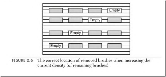
Removing some brushes will lower the total brush area if the machine is underloaded, but the machine’s complete duty cycle must be considered. (First, use the above formula to determine if this will work.)
Each brush holder must have the same number of brushes. The removed brushes must not be in line with each other. Figure 2.6 shows the right way to stagger the location of brushes.
Silicone Vapor and Adverse Ambient Conditions
Silicone vapor will cause brush dusting. Silicone grease should never be used on DC machine bearings for this reason. Forced ventilation (using outside air) is recommended when silicone contaminants can’t be avoided. Sealing vent covers and replacing gaskets with silicone will cause silicone vapors, and should be avoided.
Adverse ambient conditions affect the commutator and brushes. Air that contains caustic, corrosive, abrasive material or low humidity will shorten the life of the commutator and brushes. Clean air (with controlled humidity) will maximize the machine’s running time.
Seating Brushes
Seating brushes to fit the commutator should be done carefully. The brush face must make good contact with all segments under it. Normal operation requires segments of one or more coils to be shorted together under a brush. If full contact between brush and segments isn’t made, the magnetic neutral (explained in the next section) will shift, causing other brushes to arc. The motor will lose power and run hot. This will continue until the brushes are properly seated.
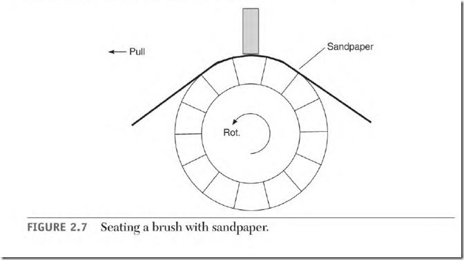
Thin sandpaper is used to do the initial seating (Fig. 2.7). It should be held against the commutator tightly, while rolling the armature or sliding the sandpaper back and forth. The final strokes should be in the direction of rotation. A seating stone can be used for the final seating.
Use a vacuum cleaner during and after this process to remove all residues. Covering the end of the commutator (risers) and the windings (up to the iron) with masking tape is recommended.
Brushes should move freely in the brush boxes and make good contact with the commutator. The brush face, which contacts the commutator, should be shiny. If any part of the brush face has a flat black color, it isn’t making good contact with the commutator.
