Transformers allow the transfer of an AC signal from one circuit to another. The transfer may involve stepping up the voltage, stepping down
the voltage, or passing the voltage unchanged.
Electromagnetic induction
If two electrically isolated coils are placed next to each other and an AC voltage is put across one coil, a changing magnetic field results. This changing mag- netic field induces a voltage into the second coil. This action is referred to as electromagnetic induction. The device is called a transformer.
In a transformer, the coil containing the AC volt- age is referred to as the primary winding. The other coil, in which the voltage is induced, is referred to as the secondary winding. The amount of voltage induced depends on the amount of mutual induction between the two coils. The amount of mutual induction is determined by the coefficient of coupling. The coefficient of coupling is a number from 0 to 1, with 1 indicating that all the primary flux lines cut the secondary windings and 0 indicating that none of the primary flux lines cut the windings.
The design of a transformer is determined by the frequency at which it will be used, the power it must handle, and the voltage it must handle. For example, the application of the transformer determines the type of core material that the coils are wound on. For low- frequency applications, iron cores are used. For high- frequency applications, air cores with nonmetallic cores used to reduce losses associated with the higher frequencies.
Transformers are rated in volt-amperes (Va) rather than in power (watts). This is because of the loads that can be placed on the secondary winding. If the load is a pure capacitive load, the reactance could cause the current to be excessive. The power rating has little meaning where a volt-ampere rating can identify the maximum current the transformer can handle.
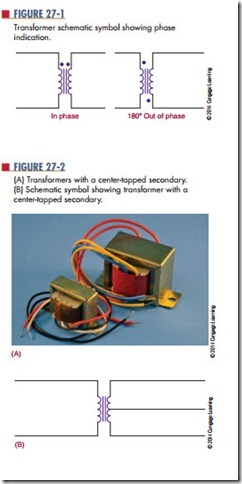
Figure 27-1 shows the schematic symbol of a transformer. The direction of the primary and secondary windings on the core determines the polarity of the induced voltage in the secondary winding. The AC voltage can either be in phase or 180° out of phase with the induced voltage. Dots are used on the schematic symbol of the transformer to indicate polarity.
Transformers are wound with tapped secondaries (Figure 27-2). A center-tapped secondary is the equivalent of two secondary windings, each with half of the total voltage across them. The center tap is used for power supply to convert AC voltages to DC voltages. A transformer may have taps on the primary to compensate for line voltages that are too high or too low.
Questions
1. How does a transformer operate?
2. What determines the design of a transformer?
3. Give an example of how the application of a transformer determines its design.
4. How are transformers rated?
Draw and label the schematic symbol for a transformer
