Working Principle of a Transformer
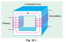
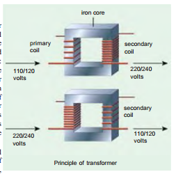
A transformer is a static (or stationary) piece of apparatus by means of which electric power in one circuit is transformed into electric power of the same frequency in another circuit. It can raise or lower the voltage in a circuit but with a corresponding decrease or increase in current. The physical basis of a transformer is mutual induction between two circuits linked by a common magnetic flux. In its simplest form, it consists of two inductive coils which are electrically separated but magnetically linked through a path of low reluctance as shown in Fig. 32.1. The two coils possess high mutual inductance. If one coil is connected to a source of alternating voltage, an alternating flux is set up in the laminated core, most of which is linked with the other coil in which it produces mutually-induced e.m.f. (according to Faraday’s Laws of Electromagnetic Induction e = MdI/dt). If the second coil circuit is closed, a current flows in it and so electric energy is transferred (entirely magnetically) from the first coil to the second coil. The first coil, in which electric energy is fed from the a.c. supply mains, is called primary winding and the other from which energy is drawn out, is called secondary winding. In brief, a transformer is a device that
1. transfers electric power from one circuit to another
2. it does so without a change of frequency
3. it accomplishes this by electromagnetic induction and
4. where the two electric circuits are in mutual inductive influence of each other.
Transformer Construction
The simple elements of a transformer consist of two coils having mutual inductance and a laminated steel core. The two coils are insulated from each other and the steel core. Other necessary parts are : some suitable container for assembled core and windings ; a suitable medium for insulating the core and its windings from its container ; suitable bushings (either of porcelain, oil-filled or capacitor-type) for insulating and bringing out the terminals
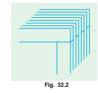
the core is constructed of transformer sheet steel laminations assembled to provide a continuous magnetic path with a minimum of air-gap included. The steel used is of high silicon content, sometimes heat treated to produce a high permeability and a low hysteresis loss at the usual operating flux densities. The eddy current loss is minimised by laminating the core, the laminations being insulated from each other by a light coat of core-plate varnish or by an oxide layer on the surface. The thickness of laminations varies from 0.35 mm for a frequency of 50 Hz to 0.5 mm for a frequency of 25 Hz. The core laminations (in the form of strips) are joined as shown in Fig. 32.2. It is seen that the joints in the alternate layers are staggered in order to avoid the presence of narrow gaps right through the cross-section of the core. Such staggered joints are said to be ‘imbricated’.
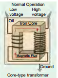
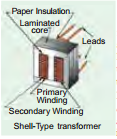
Constructionally, the transformers are of two general types, distinguished from each other merely by the manner in which the primary and secondary coils are placed around the Ground Core-type transformer Secondary Winding Shell-Type transformer laminated core. The two types are known as (i) core-type and (ii) shell- type. Another recent development is spiral-core or wound-core type, the trade name being spirakore transformer.
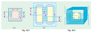
In the so-called core type transformers, the windings surround a considerable part of the core whereas in shell-type transformers, the core surrounds a considerable portion of the windings as shown schematically in Fig. 32.3 (a) and (b) respectively.
In the simplified diagram for the core type transformers [Fig. 32.3 (a)], the primary and secondary winding are shown located on the opposite legs (or limbs) of the core, but in actual construction, these are always interleaved to reduce leakage flux. As shown in Fig. 32.4, half the primary and half the secondary winding have been placed side by side or concentrically on each limb, not primary on one limb (or leg) and the secondary on the other.
In both core and shell-type transformers, the individual laminations are cut in the form of long strips of L’s, E’s and I’s as shown in Fig. 32.5. The assembly of the complete core for the two types of transformers is shown in Fig. 32.6 and Fig. 32.7.
As said above, in order to avoid high reluctance at the joints where the laminations are butted against each other, the alternate layers are stacked differently to eliminate these joints as shown in Fig. 32.6 and Fig. 32.7.
32.3. Core-type Transformers
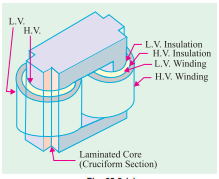
The coils used are form-wound and are of the cylindrical type. The general form of these coils may be circular or oval or rectangular. In small size core-type transformers, a simple rectangular core is used with cylindrical coils which are either circular or rectangular in form. But for large-size core-type transformers, round
or circular cylindrical coils are used which are so wound as to fit over a cruciform core section as shown in Fig. 32.8(a). The circular cylindrical coils are used in most of the core-type transformers because of their mechanical strength. Such cylindrical coils are wound in helical layers with the different layers insulated from each other by paper, cloth, micarta board or cooling ducts. Fig. 32.8(c) shows the general arrangement of these coils with respect to the core. Insulating cylinders of fuller board are used to separate the cylindrical windings from the core and from each other. Since the low- voltage (LV) winding is easiest to insulate, it is placed nearest to the core (Fig. 32.8).
Because of laminations and insulation, the net or effective core area is reduced, due allowance for which has to be made (Ex. 32.6). It is found that, in general, the reduction in core sectional area due to the presence of paper, surface oxide etc. is of the order of 10% approximately.
As pointed out above, rectangular cores with rectangular cylindrical coils can be used for small-size core-type transformers as shown in Fig. 32.9 (a) but for large-sized transformers, it becomes wasteful to use rectangular cylindrical coils and so circular cylindrical coils are preferred. For such purposes, square cores may be used as shown in Fig. 32.9 (b) where circles represent the tubular former carrying the coils. Obviously, a considerable amount of useful space is still wasted. A common improvement on square core is to employ cruciform core as in Fig. 32.9 (c) which demands, at least, two sizes of core strips. For very large transformers, further core-stepping is done as in Fig. 32.9 (d) where at least three sizes of core plates are necessary. Core-stepping not only gives high space factor but also results in reduced length of the mean turn and the consequent I2R loss. Three stepped core is the one most commonly used although more steps may be used for very large transformers as in Fig. 32.9 (e). From the geometry of Fig. 32.9, it can be shown that maximum gross core section for Fig. 32.9 (b) is 0.5 d2 and for Fig. 32.9 (c) it is 0.616 d2 where d is the diameter of the cylindrical coil.
