Transformer with Losses but no Magnetic Leakage
We will consider two cases (i) when such a transformer is on no load and (ii) when it is loaded.
Transformer on No-load
In the above discussion, we assumed an ideal transformer i.e. one in which there were no core losses and copper losses. But practical conditions require that certain modifications be made in the foregoing theory. When an actual transformer is put on load, there is iron loss in the core and copper loss in the windings (both primary and secondary) and these losses are not entirely negligible.
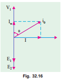
Even when the transformer is on no-load, the primary input current is not wholly reactive. The primary input current under no-load conditions has to supply (i) iron losses in the core i.e. hysteresis loss and eddy current loss and (ii) a very small amount of copper loss in primary (there being no Cu loss in secondary as it is open). Hence, the no-load primary input current I0 is not at 90° behind V1 but lags it by an angle f0 < 90°. No-load input power
where cos f0 is primary power factor under no-load conditions. No-load V1 As seen from Fig. 32.16, primary current I0 has two components : Iw
(i) One in phase with V 1. This is known as active or working or 0
iron loss component Iw because it mainly supplies the iron loss plus small quantity of primary Cu loss.
The following points should be noted carefully :
1. The no-load primary current I0 is very small as compared to the full-load primary current. It is about 1 per cent of the full-load current.
2. Owing to the fact that the permeability of the core varies with the instantaneous value of the exciting current, the wave of the exciting or magnetising current is not truly sinusoidal. As such it should not be represented by a vector because only sinusoidally varying quantities are represented by rotating vectors. But, in practice, it makes no appreciable difference.
3. As I0 is very small, the no-load primary Cu loss is negligibly small which means that no-load primary input is practically equal to the iron loss in the transformer.
4. As it is principally the core-loss which is responsible for shift in the current vector, angle f0 is known as hysteresis angle of advance.
Example 32.9. (a) A 2,200/200-V transformer draws a no-load primary current of 0.6 A and absorbs 400 watts. Find the magnetising and iron loss currents.
(b) A 2,200/250-V transformer takes 0.5 A at a p.f. of 0.3 on open circuit. Find magnetising and working components of no-load primary current.
Solution. (a) Iron-loss current
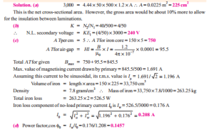
Example 32.10. A single-phase transformer has 500 turns on the primary and 40 turns on the secondary winding. The mean length of the magnetic path in the iron core is 150 cm and the joints are equivalent to an air-gap of 0.1 mm. When a p.d. of 3,000 V is applied to the primary, maximum flux density is 1.2 Wb/m2. Calculate (a) the cross-sectional area of the core (b) no-load secondary voltage (c) the no-load current drawn by the primary (d) power factor on no-load. Given that AT/cm for a flux density of 1.2 Wb/m2 in iron to be 5, the corresponding iron loss to be 2 watt/kg at 50 Hz and the density of iron as 7.8 gram/cm3.
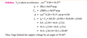
Example 32.11. A single-phase transformer has 1000 turns on the primary and 200 turns on the secondary. The no load current is 3 amp. at a p.f. of 0.2 lagging. Calculate the primary current and power-factor when the secondary current is 280 Amp at a p.f. of 0.80 lagging.
(Nagpur University, November 1997)
1. The number of turns on the primary and secondary windings of a 1-f transformer are 350 and 35 respectively. If the primary is connected to a 2.2 kV, 50-Hz supply, determine the secondary voltage on no-load. [220 V] (Elect. Engg.-II, Kerala Univ. 1980)
2. A 3000/200-V, 50-Hz, 1-phase transformer is built on a core having an effective cross-sectional area of 150 cm2 and has 80 turns in the low-voltage winding. Calculate
(a) the value of the maximum flux density in the core
(b) the number of turns in the high-voltage winding. [(a) 0.75 Wb/m2 (b) 1200]
3. A 3,300/230-V, 50-Hz, 1-phase transformer is to be worked at a maximum flux density of 1.2 Wb/m2 in the core. The effective cross-sectional area of the transformer core is 150 cm2. Calculate suitable values of primary and secondary turns. [830; 58]
4. A 40-kVA, 3,300/240-V, 50 Hz, 1-phase transformer has 660 turns on the primary. Determine
(a) the number of turns on the secondary
(b) the maximum value of flux in the core
(c) the approximate value of primary and secondary full-load currents.
Internal drops in the windings are to be ignored.
[(a) 48 (b) 22.5 mWb (c) 12.1 A; 166.7 A]
5. A double-wound, 1-phase transformer is required to step down from 1900 V to 240 V, 50-Hz. It is to have 1.5 V per turn. Calculate the required number of turns on the primary and secondary windings respectively.
The peak value of flux density is required to be not more than 1.2 Wb/m2. Calculate the required cross-sectional area of the steel core. If the output is 10 kVA, calculate the secondary current.
[1,267; 160; 56.4 cm2; 41.75 A]
6. The no-load voltage ratio in a 1-phase, 50-Hz, core-type transformer is 1,200/440. Find the number of turns in each winding if the maximum flux is to be 0.075 Wb.
[24 and 74 turns]
7. A 1-phase transformer has 500 primary and 1200 secondary turns. The net cross-sectional area of the core is 75 cm2. If the primary winding be connected to a 400-V, 50 Hz supply, calculate.
(i) the peak value of flux density in the core and (ii) voltage induced in the secondary winding.
[0.48 Wb/m2; 60 V]
8. A 10-kVA, 1-phase transformer has a turn ratio of 300/23. The primary is connected to a 1500-V, 60 Hz supply. Find the secondary volts on open-circuit and the approximate values of the currents in the two windings on full-load. Find also the maximum value of the flux.
[115 V; 6.67 A; 87 A; 11.75 mWb]
9. A 100-kVA, 3300/400-V, 50 Hz, 1 phase transformer has 110 turns on the secondary. Calculate the approximate values of the primary and secondary full-load currents, the maximum value of flux in the core and the number of primary turns.
How does the core flux vary with load ?
[30.3 A; 250 A; 16.4 mWb; 907]
10. The no-load current of a transformer is 5.0 A at 0.3 power factor when supplied at 230-V, 50-Hz. The number of turns on the primary winding is 200. Calculate (i) the maximum value of flux in the core (ii) the core loss (iii) the magnetising current.
[5.18 mWb; 345 W; 4.77 A]
11. The no-load current of a transformer is 15 at a power factor of 0.2 when connected to a 460-V, 50-Hz supply. If the primary winding has 550 turns, calculate
(a) the magnetising component of no-load current
(b) the iron loss
(c) the maximum value of the flux in the core.
[(a) 14.7 A (b) 1,380 W (c) 3.77 mWb]
12. The no-load current of a transformer is 4.0 A at 0.25 p.f. when supplied at 250-V, 50 Hz. The number of turns on the primary winding is 200. Calculate
(i) the r.m.s. value of the flux in the core (assume sinusoidal flux)
(ii) the core loss
(iii) the magnetising current.
[(i) 3.96 mWb (ii) 250 W (iii) 3.87 A]
13. The following data apply to a single- phase transformer:
output : 100 kVA, secondary voltage; 400 V; Primary turns: 200; secondary turns: 40; Neglecting the losses, calculate: (i) the primary applied voltage (ii) the normal primary and secondary currents (iii) the secondary current, when the load is 25 kW at 0.8 power factor.
(Rajiv Gandhi Technical University, Bhopal 2000) [(i) 2000 V, (ii) 50 amp, (iii) 78.125 amp]


