Three-phase to Two-phase Conversion and vice-versa
This conversion is required to supply two-phase furnaces, to link two-phase circuit with 3-phase sys- tem and also to supply a 3-phase apparatus from a 2-phase supply source. For this purpose, Scott connection as shown in Fig. 33.17 is employed. This connection requires two transformers of different ratings although for interchangeability and provision of spares, both transformers may be identical but having suitable tappings.
If, in the secondaries of Fig. 33.14 (b), points c and d are connected as shown in Fig. 33.18 (b), then a 2-phase, 3-wire system is obtained. The voltage Edc is 86.6 V but ECb = 100 V, hence the resulting 2-phase voltages will be unequal. However, as shown in Fig. 33.19 (a) if the 3-phase line is connected to point A1, such that DA1 represents 86.6% of the teaser primary turns (which are the same as that of main primary), then this will increase the volts/turn in the ratio of 100 : 86.6, because now 86.6 volts are applied across 86.6 per cent of turns and not 100% turns. In other words, this will make volts/ turn the same both in primary of the teaser and that of the main transformer. If the secondaries of both the transformers have the same number of turns, then secondary voltage will be equal in magnitude as shown, thus resulting in a symmetrical 2-phase, 3-wire system.
Consider the same connection drawn slightly differently as in Fig. 33.20. The primary of the main transformer having N1 turns is connected between terminals CB of a 3-phase supply. If supply line voltage is V, then obviously VAB = VBC = VCA = V but voltage between A and D is V ´ 3/ 2. As said
above, the number of turns between A and D should be also ( 3 / 2) N1 for making volt/turn the same in both primaries. If so, then for secondaries having equal turns, the secondary terminal voltages will be equal in magnitude although in phase quadrature.
Hence, the currents in the lines B and C are obtained vectorially as shown in Fig. 33.22. It should be noted that as the two halves of the teaser primary current flow in opposite directions from point D, they have no magnetic effect on the core and play no part at all in balancing the secondary ampere-turns of the main transformer.
The line currents thus have rectangular components of KI2M and 0.58, KI2T and, as shown in Fig. 33.22, are in phase with the primary star voltages VNB and VNC and are equal to the teaser primary current. Hence, the three-phase side is balanced when the two-phase load of unity power factor is balanced.
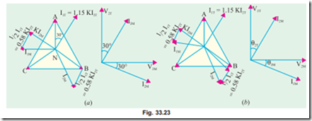
Fig. 33.23 (a) illustrates the condition corresponding to a balanced two-phase load at a lagging power factor of 0.866. The construction is the same as in Fig. 33.22. It will be seen that the 3-phase side is again balanced. But under these conditions, the main transformer rating is 15% greater than that of the teaser, because its voltage is 15% greater although its current is the same.
Hence, we conclude that if the load is balanced on one side, it would always be balanced on the other side.
The conditions corresponding to an unbalanced two-phase load having different currents and power factors are shown in Fig. 33.23 (b). The geometrical construction is similar to those explained in Fig. 33.22 and (a).
Summarizing the above we have :
1. Teaser transformer primary has 3/ 2 times the turns of main primary. But volt/turn is the same. Their secondaries have the same turns which results in equal secondary terminal voltages.
2. If main primary has N1 turns and main secondary has N2 turns, then main transformation ratio is
3. If the load is balanced on one side, it is balanced on the other side as well.
4. Under balanced load conditions, main transformer rating is 15% greater than that of the teaser.
5. The currents in either of the two halves of main primary are the vector sum
Example 33.18. Two transformers are required for a Scott connection operating from a 440-V, 3-phase supply for supplying two single-phase furnaces at 200 V on the two-phase side. If the total output is 150 kVA, calculate the secondary to primary turn ratio and the winding currents of each transformer.
Note. We have made use of the fact that since secondary load is balanced, primary load is also balanced. If necessary, I1M can also be found.
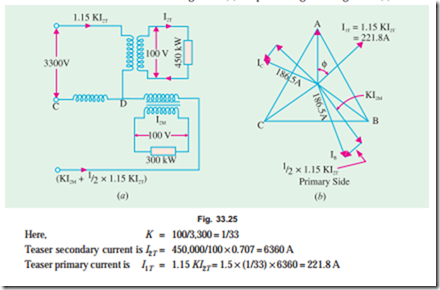
Example 33.20. In a Scott-connection, calculate the values of line currents on the 3-phase side if the loads on the 2-phase side are 300 kW and 450 kW both at 100 V and 0.707 p.f. (lag) and the 3-phase line voltage is 3,300 V. The 300-kW load is on the leading phase on the 2-phase side. Neglect transformer losses. (Elect. Technology, Allahabad Univ. 1991)
Solution. Connections are shown in Fig. 33.25 (a) and phasor diagram in Fig. 33.25 (b).
Example 33.21. Two electric furnaces are supplied with 1-phase current at 80 V from a 3-phase, 11,000 V system by means of two single-phase Scott-connected transformers with similar secondary windings. When the load on one furnace is 500 kW (teaser secondary) and on the other 800 kW (secondary of main transformer) what current will flow in each of the 3-phase lines (a) at unity power factor and (b) at 0.5 power factor ? Neglect phase displacement in and efficiency of, the transformers. (Electrical Engineering, Madras Univ. 1987)
Solution. The connections are shown in Fig. 33.26 and the phasor diagrams for unity and 0.5 p.f. are shown in Fig. 33.27 (a) and (b) respectively.
Example 33.23. Two single-phase Scott-connected transformers supply a 3-phase four-wire distribution system with 231 volts between lines and the neutral. The h.v. windings are connected to a two-phase system with a phase voltage of 6,600 V. Determine the number of turns in each section of the h.v. and l.v. winding and the position of the neutral point if the induced voltage per turn is 8 volts.
Solution. As the volt/turn is 8 and the h.v. side voltage is 6,600 V, the h.v. side turns are = 6,600/8 = 825 on both transformers.
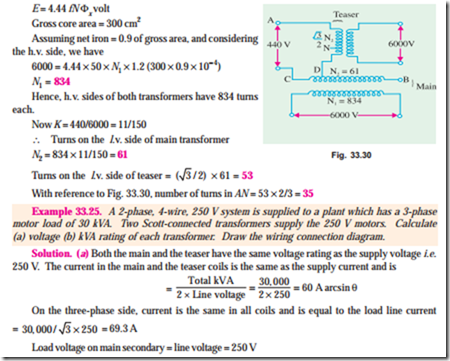
Example 33.24. A Scott-connected (2 to 3-phase) transformer links a 6,000 V, 2-phase system with a 440 V; 3-phase system. The frequency is 50 Hz, the gross core area is 300 cm2, while the maximum flux density is to be about 1.2 Wb/m2. Find the number of turns on each winding and the point to be tapped for the neutral wire on the 3-phase side. If the load is balanced on the one side of such a transformer, find whether it will also be balanced on the other side. (London Univ.)
Solution. Use the transformer voltage equation 1,
Tutorial Problem No. 33.3
1. A Scott-connected transformer is fed from a 6,600-V, 3-phase network and supplies two single-phase furnaces at 100 V. Calculate the line currents on the 3-phase side when the furnaces take 400 kW and 700 kW respectively at 0.8 power factor lagging. (Elect. Machines II, Indore Univ. 1977)
[With 400 kW on teaser, line currents are 87. 2 A; 139 A; 139 A]
2. Two 220-V, 1-phase electrical furnaces take loads of 350 kW and 500 kW respectively at a power factor of 0.8 lagging. The main supply is at 11-kV, 3-phase, 50 Hz. Calculate current in the 3-phase lines which energise a Scott-connected transformer combination. (Elect. Machines, Madras Univ. 1978)
[With 350 kW on teaser line currents are : 45.7 A ; 61.2 A; 61.2 A]
3. Two electric furnaces are supplied with 1-phase current at 80 V from 3-phase, 11,000-V supply mains by means of two Scott-connected transformers with similar secondary windings. Calculate the current flowing kW respectively in each of the 3-phase lines at U.P.P. when the loads on the two transformers are 550 kW of 800 kW.
[With 550 kW on teaser, line currents are : 57.5 A; 78.2; 78.2 A] (Electrical Machines-I, Madras University, 1977)


