STARTING INDUCTION MOTORS
Since the inrush current of induction motors can exceed 8 times the normal operating current, across-the-line starting may not be acceptable because it may cause a dip in the power system voltage. In wound rotor induction motors, extra resistance can be inserted in the rotor circuit during starting. This results in an increase in the starting torque and a reduction in the starting current. The starting current of a squirrel-cage induction motor can vary widely depending on the motor’s rated power and the effective resistance of the rotor at starting conditions.
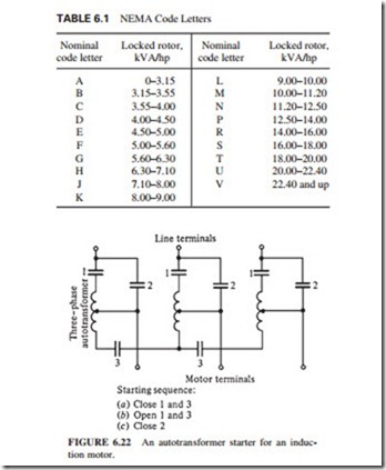
A starting code letter has been established to estimate the rotor current when the motor is starting. This code letter sets the limit on the magnitude of the current that the motor can draw at starting conditions. These limits are given in terms of the starting apparent power of the motor as a function of its horsepower rating. Table 6.1 shows the starting kVA per horsepower for each code letter. The NEMA code letters indicate the starting kilovoltam- peres per horsepower of rating for a motor. Each code letter extends up to, but does not include, the lower bound of the next higher class.
The starting current of an induction motor can be determined by
The starting current can be reduced if necessary, by a starting circuit. However, this results in reduction of the starting torque of the motor. The starting current of an induction motor can be reduced by inserting extra inductors or resistors in the power line during starting conditions. Alternatively, the terminal voltage of the motor can be reduced during starting by using an autotransformer to step it down.
Figure 6.22 illustrates a typical reduced-voltage starting circuit using autotransformers. During start-up, contacts 1 and 3 are shut. The voltage supplied to the motor is lower than
normal. When the motor approaches the operating speed, those contacts are opened, and contact 2 is shut, putting the full line voltage across the motor.
When the starting current is reduced proportionally to the decrease in terminal voltage,the starting torque decreases proportionally to the square of the applied voltage. Hence, the reduction in starting current is limited when the motor is coupled to a load.
Induction Motor Starting Circuits
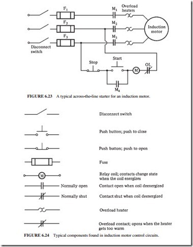
Figure 6.23 illustrates a typical full-voltage or across-the-line induction motor starter circuit. The meanings of the symbols are explained in Fig. 6.24. When the start button is
pressed, the coil of relay (or contactor) M is energized, causing normally open contacts M1, M2, and M3 to close. When these contacts close, power is applied to the motor. Also, contact M4 closes, shorting out the starting switch, allowing the operator to release the switch while relay M remains energized. When the stop button is pressed, relay M deenergizes, stopping the motor.
The built-in protective features in this type of magnetic motor starter circuit are
1. Short-circuit protection
2. Overload protection
3. Undervoltage protection
Fuses F1, F2, and F3 provide short-circuit protection for the motor. When a short circuit occurs, the current increases instantly to many times the rated value. The fuses blow, dis- connecting the motor from the power supply to prevent it from burning up.
However, these fuses are designed to tolerate currents many times greater than the full-load current. They would not burn up during normal starting due to inrush current. Therefore, if a short circuit occurs through a high resistance and/or excessive loads, it will not be cleared by the fuses.
The devices labeled OL provide the overload protection for the motor. They consist of two parts: the overload heater element and overload contacts. During normal operation, the overload contacts are closed. When the temperature of the heater elements increases to a set limit, the OL contacts open. This deenergizes the M relay opening the M contacts and isolating the motor from the power supply. If the motor is overloaded for an extended period of time, damage will occur due to the excessive heating caused by the high currents. The inrush current would not affect the heater elements because of its short duration. The heater elements will operate when there is a high current for an extended period, isolating the motor from the power supply.
The controller provides the undervoltage protection. The control power for the M relay comes from directly across the incoming lines to the motor. If the voltage level drops beyond a certain level, the voltage applied to the M relay will also fall, resulting in the deenergization of the relay.
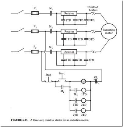
Figure 6.25 illustrates an induction motor starting circuit with resistors to reduce the starting current. Relays 1TD, 2TD, and 3TD are on-time delay relays. When these relays are energized, there is a set time delay before their contacts close.
When the start button is pushed, the M relay gets energized. Its contacts close, allowing power to reach the motor. Since the contacts for the 1TD, 2TD, and 3TD relays are all open, the current is forced to flow through the full starting resistor, reducing the starting current. The 1TD relay gets energized as soon as the contacts of the M relay close. However, there is a set time delay before the contacts of the 1TD relay close. During this time, the motor would have gained some speed, and the starting current decreased.
After the specified time delay, the contacts of the 1TD relay close, cutting out the first part of the starting resistance and simultaneously causing relay 2TD to energize. After another delay, the contacts for relay 2TD close, cutting out the second part of the starting resistor and causing relay 3TD to energize. Finally, the contacts of relay 3TD close, causing the resistor to be bypassed.
The values of the resistor and time delays can be selected to prevent the starting current from becoming dangerously large while allowing enough current to ensure adequate accel- eration to the normal operating speed.


