Open-Delta or V – V connection
If one of the transformers of a D – D is removed and 3-phase supply is connected to the primaries as shown in Fig. 33.11, then three equal 3-phase voltages will be available at the secondary terminals on no- load. This method of transforming 3-phase power by means of only two transformers is called the open – D or V – V connection.
It is employed :
1. when the three-phase load is too small to warrant the installation of full three-phase transformer bank.
2. when one of the transformers in a D – D bank is disabled, so that service is continued although at reduced capacity, till the faulty transformer is repaired or a new one is substituted.
3. when it is anticipated that in future the load will increase necessitating the closing of open delta.
One important point to note is that the total load that can be carried by a V – V bank is not two-third of the capacity of a D – D bank but it is only 57.7% of it. That is a reduction of 15% (strictly, 15.5%) from its normal rating.
Suppose there is D – D bank of three 10-kVA transformers. When one transformer is removed, then it runs in V – V. The total rating of the two transformers is 20 kVA. But the capacity of the V – V bank is not the sum of the transformer kVA ratings but only 0.866 of it i.e. 20 ´ 0.866 = 17.32 (or 30 ´ 0.57 = 17.3 kVA). The fact that the ratio of V-capacity to D-capacity is 1/ 3 = 57.7% (or nearly 58%) instead of 66 2 per cent can be proved as follows :
It is obvious from above that when one transformer is removed from a D – D bank.
1. the bank capacity is reduced from 30 kVA to 30 ´ 0.577 = 17.3 kVA and not to 20 kVA as might be thought off-hand.
2. only 86.6% of the rated capacity of the two remaining transformers is available (i.e. 20 ´ 0.866 = 17.3 kVA). In other words, ratio of operating capacity to available capacity of an open-D is 0.866. This factor of 0.866 is sometimes called the utility factor.
3. each transformer will supply 57.7% of load and not 50% when operating in V – V (Ex. 33.13).
However, it is worth noting that if three transformers in a D – D bank are delivering their rated load* and one transformer is removed, the overload on each of the two remaining transformers is 73.2% because
This over-load may be carried temporarily but some provision must be made to reduce the load if overheating and consequent breakdown of the remaining two transformers is to be avoided.
The disadvantages of this connection are :
1. The average power factor at which the V-bank operates is less than that of the load. This power factor is actually 86.6% of the balanced load power factor. Another significant point to note is that, except for a balanced unity power factor load, the two transformers in the V – V bank operate at different power factors (Art. 33.8).
2. Secondary terminal voltages tend to become unbalanced to a great extent when the load is in- creased, this happens even when the load is perfectly balanced.
It may, however, be noted that if two transformers are operating in V – V and loaded to rated capacity (in the above example, to 17.3 kVA), the addition of a third transformer increases the total capacity by 3 or 173.2% (i.e. to 30 kVA). It means that for an increase in cost of 50% for the third transformer, the increase in capacity is 73.2% when converting from a V – V system to a D – D system.
Power Supplied by V – V Bank
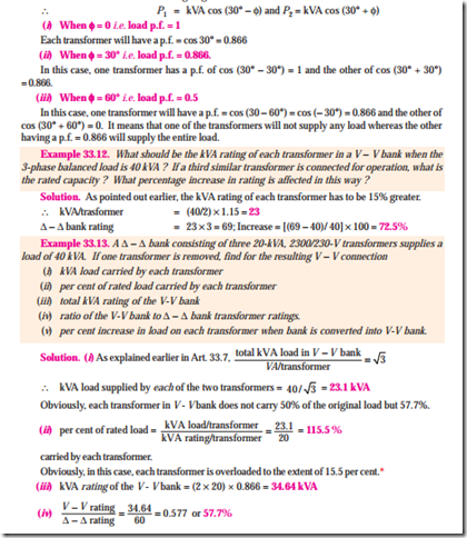
When a V – V bank of two transformers supplies a balanced 3-phase load of power factor cos f, then one transformer operates at a p.f. of cos (30° – f) and the other at cos (30° + f). Consequently, the two transformers will not have the same voltage regulation.
It is obvious that each transformer in the D – D bank supplying 40 kVA was running underloaded (13.33 vs 20 kVA) but runs overloaded (23.1 vs 20 kVA) in V – V connection.
Example 33.14. A balanced 3-phase load of 150 kW at 1000 V, 0.866 lagging power factor is supplied from 2000 V, 3-phase mains through single-phase transformers (assumed to be ideal) connected in (i) delta-delta (ii) Vee-Vee. Find the current in the windings of each transformer and the power factor at which they operate in each case. Explain your calculations with circuit and vector diagrams.
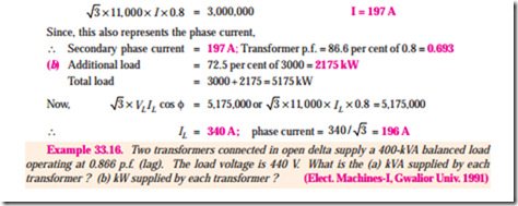
Example 33.15. (a) Two identical 1-phase transformers are connected in open-delta across 3-phase mains and deliver a balanced load of 3000 kW at 11 kV and 0.8 p.f. lagging. Calculate the line and phase currents and the power factors at which the two transformers are working.
(b) If one more identical unit is added and the open delta is converted to closed delta, calculate the additional load of the same power factor that can now be supplied for the same temperature rise. Also calculate the phase and line currents. (Elect. Machinery-I, Madras Univ. 1987)
Solution. (a) If I is the line current, then
Solution. As stated in Art 33.7, the ratio of operating capacity to available capacity in an open-D is 0.866. Hence, kVA of each transformer is one-half of the total kVA load divided by 0.866.
Tutorial Problem No. 33.2
1. Three 1100/110-V transformers connected delta-delta supply a lighting load of 100 kW. One of the transformers is damaged and removed for repairs. Find
(a) What currents were flowing in each transformer when the three transformers were in service ?
(b) What current flows in each transformer when the third is removed ? and
(c) The output kVA of each transformer if the transformers connected in open D supply the full-load with normal heating ?


