Testing the Triac
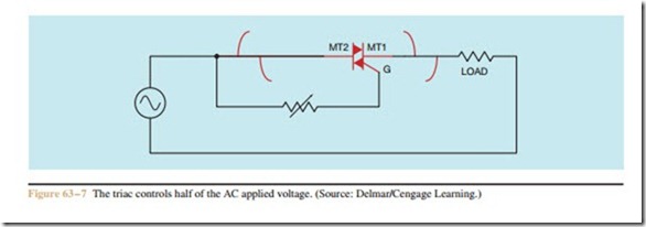
The triac can be tested with an ohmmeter (see Procedure 5 in the Appendix). To test the triac, connect the ohmmeter leads to MT2 and MT1. The ohmmeter should indicate no continuity. If the gate lead is touched to MT2, the triac should turn on and the ohmmeter should indicate continuity through the triac. When the gate lead is released from MT2, the triac may continue to conduct or it may turn off, depending on whether the ohmmeter supplies enough current to keep the de- vice above its holding current level. This tests one half of the triac.
To test the other half of the triac, reverse the connection of the ohmmeter leads. The ohmmeter should indicate no continuity. If the gate is touched again to MT2, the ohmmeter should indicate continuity through the device. The other half of the triac has been tested.
Review Questions
1. Draw the schematic symbol for a triac.
2. When a triac is connected in an AC circuit, is the output AC or DC?
3. The triac is a member of what family of devices?
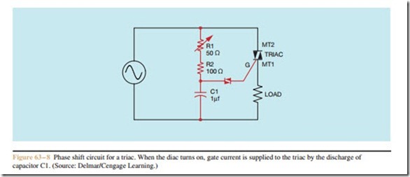
4. Briefly explain why a triac must be phase shifted.
5. What electronic component is frequently used to phase shift the triac?
6. When the triac is being tested with an ohmmeter, which other terminal should the gate be connected to if the ohmmeter is to indicate continuity?

