TRANSFORMER RATINGS
Transformers have ratings for apparent power, voltage, current, and frequency.
Voltage and Frequency Ratings of a Transformer
The voltage rating of a transformer is used to protect the winding insulation from failure due to high voltage applied to it. It also has a second purpose associated with the
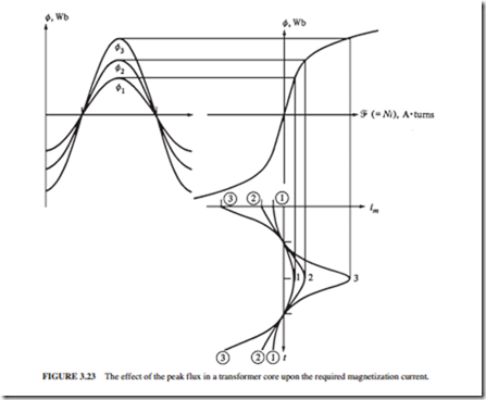
magnetization current of the transformer. Figure 3.8a illustrates the magnetization curve of a transformer. When a voltage υ(t) = VM sin wt V is applied to the primary winding of the trans- former, the flux will be
A 5 percent increase in the applied voltage υ (t) will increase the flux in the core by 5 percent. However, in the saturation region, a 5 percent increase in flux requires a much larger increase in the magnetization current than 5 percent (Fig. 3.23). Thus, at a specified voltage, this high magnetization current starts to damage the insulation. The rated voltage is determined by the maximum acceptable magnetization current.
Since the flux is proportional to V/w, a transformer designed for 60-Hz operation can be operated on 50 Hz if the applied voltage is reduced by one-sixth. This is known as de- rating the transformer. Similarly, a transformer designed for 50-Hz operation can have 20 percent higher voltage when operated at 60 Hz if its insulation system can withstand the higher voltage.
Apparent Power Rating of a Transformer
The apparent power rating of a transformer is used in conjunction with the voltage rating to determine the maximum allowable current in the transformer. Since the heat losses are proportional to i2R, the current must be limited to prevent a significant reduction in the life of the insulation due to overheating.
If the transformer is operated at a lower frequency than normal (say, 50 Hz rather than 60 Hz) and its applied voltage is reduced as discussed above, its apparent power rating must be reduced by an equal amount. This is done to prevent overheating.
Inrush Current
The inrush current to the transformer is around 12 times the normal operating current. It usually lasts 8 to 10 cycles. The transformer and the power system connected to it must be able to withstand these high currents.
Transformer Nameplate
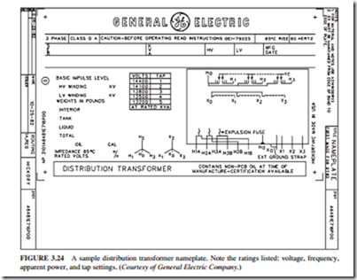
Figure 3.24 illustrates a typical nameplate for a distribution transformer. The information on the nameplate includes
● Rated voltage
● Rated apparent power
● Rated frequency
● Transformer impedance
● Voltage rating for each tap on the transformer
● Wiring schematic of the transformer
● Transformer type designation
● References to operating instructions
Instrument Transformers
Potential transformers and current transformers are two special-purpose transformers used for taking measurements.
Potential transformer is used to sample the voltage of a power system. It has high voltage on the primary side and low voltage on the secondary. Its power rating is low. These transformers are manufactured with different accuracy classes.
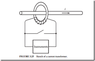
Current transformer is used to sample the current in a line (Fig. 3.25). Its secondary wind- ing is wrapped around a ferromagnetic ring while the single primary line goes through the center of the ring. A typical rating of a current transformer includes 600 : 5 and 1000 : 5. Extremely high voltages will appear across the secondary terminals of a current trans- former if the terminals are open. The current transformer should always be kept short- circuited to prevent dangerous high voltages from appearing at the secondary terminals.


