Simplified Diagram
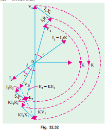
The vector diagram of Fig. 32.29 may be considerably simplified if the no-load current I0 is neglected. Since I0 is 1 to 3 per cent of full-load primary current I1, it may be neglected without serious error. Fig. 32.32 shows the diagram of Fig. 32.29 with I0 omitted altogether.
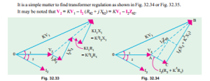
In Fig. 32.32, V2, V 1, f2 are known, hence E2 can be found by adding vectorially I2 R2 and I2 X 2 to V 2. Similarly, V 1 is given by the vector addition of I1 R1 and I1 X 1 to E1. All the to the secondary side as shown in figure, where the upper part of the diagram has been rotated through 180°. However, it should be noted that each voltage or voltage drop should be multiplied by transformation ratio K.
The lower side of the diagram has been shown separately in Fig. 2.34 laid horizontally where vector for V 2 has been taken along X-axis.
Total Approximate Voltage Drop in a Transformer
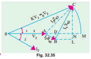
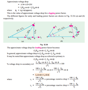
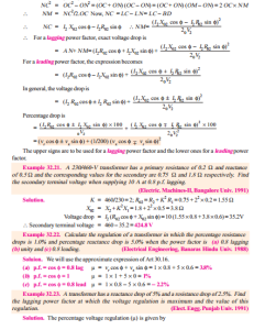
When the transformer is on no-load, then V 1 is ap- proximately equal to E1. Hence E2 = KE1 = K V1. Also, E2 = 0V 2 where 0V2 is secondary terminal voltage on no– 0 load, hence no-load secondary terminal voltage is K V1. The secondary voltage on load is V2. The difference be- tween the two is I2 Z02 as shown in Fig. 32.35. The approximate voltage drop of the transformer as referred to secondary is found thus :
With O as the centre and radius OC draw an arc cutting OA produced at M. The total voltage drop I2 Z02 = AC = AM which is approximately equal to A N. From B draw BD perpendicular on OA produced. Draw CN perpendicular to OM and draw BL parallel to OM.
Exact Voltage Drop
With reference to Fig. 32.35, it is to be noted that exact voltage drop is AM and not A N. If we add the quantity NM to A N, we will get the exact value of the voltage drop.
Considering the right-angled triangle OCN, we get
