Regulation of a Transformer
1. When a transformer is loaded with a constant primary voltage, the secondary voltage decreases* because of its internal resistance and leakage reactance.
Let 0V2 = secondary terminal voltage at no-load.
= E2 = EK1 = K V1 because at no-load the impedance drop is negligible.
V2 = secondary terminal voltage on full-load.
The change in secondary terminal voltage from no-load to full-load is = 0V2 – V2. This change divided by 0V2 is known as regulation ‘down’. If this change is divided by V2, i.e., full-load secondary terminal voltage, then it is called regulation ‘up’.
The lesser this value, the better the transformer, because a good transformer should keep its secondary terminal voltage as constant as possible under all conditions of load.
(2) The regulation may also be explained in terms of primary values.
In Fig. 32.51 (a) the approximate equivalent circuit of a transformer is shown and in Fig. 32.51 (b), (c) and (d) the vector diagrams corresponding to different power factors are shown.
The secondary no-load terminal voltage as referred to primary is E¢2 = E2/K = E1 = V 1 and if the secondary full-load voltage as referred to primary is V 2¢ (= V 2/K) then
As the transformer is loaded, the secondary terminal voltage falls (for a lagging p.f.). Hence, to keep the output voltage constant, the primary voltage must be increased. The rise in primary voltage required to maintain rated output voltage from no-load to full-load at a given power factor expressed as percentage of rated primary voltage gives the regulation of the transformer.
Suppose primary voltage has to be raised from its rated value V1 to V1¢, then
Example 32.43. A-100 kVA transformer has 400 turns on the primary and 80 turns on the secondary. The primary and secondary resistances are 0.3 W and 0.01 W respectively and the corresponding leakage reactances are 1.1 and 0.035 W respectively. The supply voltage is 2200 V. Calculate (i) equivalent impedance referred to primary and (ii) the voltage regulation and the sec- ondary terminal voltage for full load having a power factor of 0.8 leading.
(Elect. Machines, A.M.I.E. Sec. B, 1989)
(Nagpur University, November 1997)
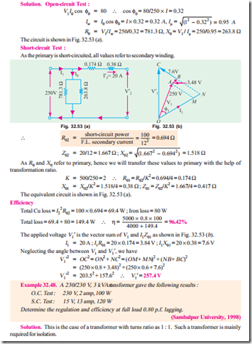
Solution. (a) Rated current on L.V. side = 10,000/230 = 43.5 A. Let the total resistance and total leakage reactance be referred to L.V. side. Finally, the required H.V. side voltage can be worked out after transformation.
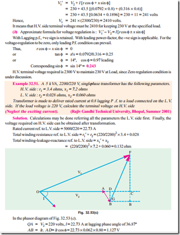
For purpose of calculation of voltage-magnitudes, approximate formula for voltage regulation can be used. For the present case of 0.8 lagging p.f.


