Open-circuit or No-load Test
The purpose of this test is to determine no-load loss or core loss and no-load I0 which is helpful in finding X0 and R0.
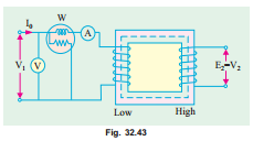
One winding of the transformer – whichever is convenient but usually high voltage winding – is left open and the other is connected to its supply of normal voltage and frequency. A wattmeter W, voltmeter V and an ammeter A are connected in the low- voltage winding i.e. primary winding in the present case. With normal voltage applied to the primary, normal flux will be set up in the core, hence normal iron losses will occur which are recorded by the wattmeter. As the primary no-load current I0 (as measured by ammeter) is small (usually 2 to 10% of rated load current), Cu loss is negligibly small in primary and nil in secondary (it being open). Hence, the wattmeter reading represents practically the core loss under no-load condition (and which is the same for all loads as pointed out in Art. 32.9).
It should be noted that since I0 is itself very small, the pressure coils of the wattmeter and the voltmeter are connected such that the current in them does not pass through the current coil of the wattmeter.
Sometimes, a high-resistance voltmeter is connected across the secondary. The reading of the voltmeter gives the induced e.m.f. in the secondary winding. This helps to find transformation ratio K.
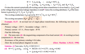
The no-load vector diagram is shown in Fig. 32.16. If W is the wattmeter reading (in Fig. 32.43), then


