Elementary Theory of an Ideal Transformer
An ideal transformer is one which has no losses i.e. its windings have no ohmic resistance, there is no magnetic leakage and hence which has no I2R and core losses. In other words, an ideal transformer consists of two purely inductive coils wound on a loss-free core. It may, however, be noted that it is impossible to realize such a transformer in practice, yet for convenience, we will start with such a trans-former and step by step approach an actual transformer.
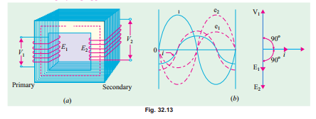
Consider an ideal transformer [Fig. 32.13 (a)] whose secondary is open and whose primary is connected to sinusoidal alternating voltage V1. This potential difference causes an alternating current to flow in the primary. Since the primary coil is purely inductive and there is no output (secondary being open) the primary draws the magnetising current Iµ only. The function of this current is merely to magnetise the core, it is small in magnitude and lags V 1 by 90°. This alternating current Iµ produces an alternating flux f which is, at all times, proportional to the current (assuming permeability of the magnetic circuit to be constant) and, hence, is in phase with it. This changing flux is linked both with the primary and the secondary windings. Therefore, it produces self-induced e.m.f. in the primary. This self-induced e.m.f. E1 is, at every instant, equal to and in opposition to V 1. It is also known as counter e.m.f. or back e.m.f.
of the primary.
Similarly, there is produced in the secondary an induced e.m.f. E2 which is known as mutually induced e.m.f. This e.m.f. is antiphase with V1 and its magnitude is proportional to the rate of change of flux and the number of secondary turns.
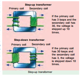
The instantaneous values of applied voltage, induced e.m.fs, flux and If the primary coil has 3 loops and the secondary coil has 30, the voltage is stepped up 10 times.
If the primary coil has 30 loops and the secondary coil has 3, the voltage is stepped down 10 times.
magnetising current are shown by sinusoidal waves in Fig. 32.13 (b). Fig. 32.13 c) shows the vectorial representation of the effective values of the above quantities.
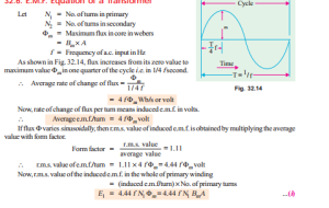
E.M.F. Equation of a Transformer


