Torque is twisting force, measured in foot-pounds, inch-pounds, and inchounces. The formula combines torque and speed (RPM) to find horsepower:
torque x RPM + 5250 = hi)
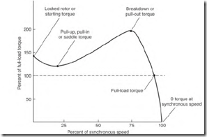
Torque and RPM terms are explained in Fig. 5.12. Understanding these terms is essential when fitting a motor to a load.
FIGURE 5.12 Torque terms from 0 RPM to synchronous speed.
Starting torque (locked rotor torque) is the amount of torque that is available to break the load away from a standstill position. (Breakaway torque is another name used for this torque value.)
Starting torque is a very important value when fitting a motor to a load. For example, an air compressor (starting against compression) requires very high starting torque.
Saddle torque is a dip in the motor’s torque output that occurs between starting and pull-out (or breakdown) RPM. If the motor’s (saddle) torque drops below the load torque demand, the motor will stop accelerating. The motor windings will overheat and fail (unless the overload protection trips).
Saddle torque is a problem found in two-pole motors that have a largediameter bore. A special connection called the interspersed connection is used to minimize saddle torque. The problem occurs when a motor has been rewound and the connection is not used.
Breakdown (or pull-out) torque is the maximum possible torque that a motor can develop, and it can occur at any RPM between starting and full load.
If breakdown torque occurs close to nameplate RPM, just a few RPM less than nameplate RPM will cause the motor to overheat.
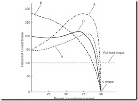
A small reduction in RPM, caused by an overload, results in a large increase in horsepower output (Fig. 5.13 design A). An increase in horsepower output is accompanied by an even larger increase in amperes (and heat).
Full-load torque is the maximum torque the motor can have continuously (without overheating). This torque occurs at the nameplate RPM.
The preceding torque values vary with rotor bar design. The motor’s design letter—found on the motor’s nameplate—identifies the torque characteristics of a motor.
Design Letter
A three-phase motor’s design letter (found on the nameplate) is a very important factor in selecting a motor. Figure 5.13 shows the torque and speed characteristics of each letter.
Design A
The design A motor has large rotor bars, so it will demand high starting current. However, despite having high starting current, it has only moderate starting torque. Therefore, the motor’s protection has to be adjusted accordingly.
FIGURE 5.13 A design letter is given to a rotor. The shape, size, and location of the rotor bars affect the design letter.
This motor has very high torque near its rated RPM. Its large rotor bars keep the rotor’s full-load speed close to the synchronous speed. (This can be compared to a paddle wheel in a stream of water; with large paddles the wheel slips very little and rotates at close to the water’s speed.) The design A motor will keep its load at nearly constant speed.
The design A motor will overheat even if it’s overloaded only a few RPM (below its nameplate rating). Higher torque (at lower speed) results in a large increase in horsepower output and ampere demand.
Some efficiency is lost with rotor slip. The torque curve of design A is similar to that of a high-efficiency motor.
Design B
Design B
Design B is a standard industrial mot0L It has average starting torque and moderate starting current. This motor has a lower full-load RPM than that of the design A or the high-efficiency motor. Most design B rotors use low-cost cast aluminum.
Design C
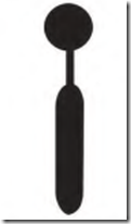
The design C motor has higher starting torque and slightly greater slip than the design B motor. Its rotor bars are two sizes, linked together. A small bar
FIGURE 5.14 The rotor bar used in a design C rotor has two shapes that are linked.
near the rotor’s surface is linked to a larger bar deeper in the iron (Fig. 5.14). The small part of the bar gives the rotor high starting torque. The deeper part will reduce the slip. Starting current is moderate, limited by the size of the small bar. The bars are usually made of copper or brass (making the motor more costly). They are more likely to crack because of their shape and the type of metal used.
Design D
Design D is for loads requiring extremely high starting torque but not high torque near rated speed. This design is suited for a heavy flywheel load or for a centrifuge load. This motor can power a heavy flywheel load up to the nameplate RPM without developing excessive heat. (Its small rotor bars limit the starting current.)
A metal shear is an example of a load that stores energy in the weight of its moving flywheel. The shear slows its motor’s RPM below the nameplate value each time it cuts metal. Because of the small rotor bars, the torque and (stator winding) amperes aren’t excessively high when the motor’s speed is lowered.
The design D motor can handle wide RPM swings without developing excess heat in its stator windings.
Design Letter Summary
Industry presents a wide range of speed and torque demands for the three-phase induction motor. Four-pole motors are the most common, followed by two-pole, then six-pole motors. There are many different torque demands, from zero to full-load speed. Some loads require very high starting (breakaway) torque. Other loads require little starting torque, but demand
higher torque as the speed increases. The design letter helps in selecting the right motor.
The design A and the high-efficiency motors develop high torque just a few RPM slower than their rated RPM. Because of this characteristic, they are the choice for loads that require a fairly constant speed.
Liquid-moving pumps and air-moving equipment have similar loading characteristics. If the RPM is increased a small amount over the rating, the horsepower demand increases to the cube of the RPM change. (The RPM of the replacement motor has to be the same as the original for this type of load.) Most three-phase induction motors operate very close to their nameplate RPM when rated load is applied. Less than rated load allows the shaft to turn at a slightly higher RPM than its nameplate value (slip can vary from 0.3 to 5 percent). Standard three-phase induction motors under 10 horsepower have greater slip than those over 10 horsepower. Slip for standard motors above 50 horsepower is 1 percent or less.


