Standard Levels and Level Meters
Suppose I asked you to put together a device comprising component parts I had previously organized from different sources. And suppose I had paid very little attention to whether each of the component parts would fit together (perhaps one part might be imperial and another metric). You would become frustrated pretty quickly because the task would be impossible. So it would be too for the audio mixer, if the signals it received were not, to some degree at least, standardized. The rationale behind these standards and the tools used in achieving this degree of standardization are the subjects of the first few sections of this chapter.
The adoption of standardized studio levels (and of their associated lineup tones) ensures the interconnectability of different equipment from different manufacturers and ensures that tapes made in one studio are suitable for replay and/or rework in another. Unfortunately, these “standards” have evolved over many years and some organizations have made different decisions, which, in turn, have reflected upon their choice of operating level. National and industrial frontiers exist too, so that the subject of maximum and alignment signal levels is fraught with complication.
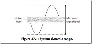
Fundamentally, only two absolute levels exist in any electronic system, maximum level, and noise floor. These are both illustrated in Figure 27.1. Any signal that is lower than the noise floor will disappear as it is swamped by noise and signal, which is larger than maximum level will be distorted. All well-recorded signals have to sit comfortably between the “devil” of distortion and the “deep blue sea” of noise. Actually, that’s the fundamental job of any recording engineer!
In principle, maximum level would make a good line-up level. Unfortunately, it would also reproduce over loudspeakers as a very loud noise indeed and would therefore, likely
as not, “fray the nerves” of those people working day after day in recording studios! Instead a lower level is used for line-up, which actually has no physical justification at all. Instead it is cleverly designed to relate maximum signal level to the perceptual mechanism of human hearing and to human sight as we shall see. Why sight? Because it really isn’t practical to monitor the loudness of an audio signal by sound alone. Apart from anything else, human beings are very bad at making this type of subjective judgement. Instead, from the very earliest days of sound engineering, visual indicators have been used to indicate audio level, thereby relieving the operator from making subjective auditory decisions. There exist two important and distinct reasons to monitor audio level.
The first is to optimize the drive, the gain or sensitivity of a particular audio circuit, so that the signal passing through it is at a level whereby it enjoys the full dynamic range available from the circuit. If a signal travels through a circuit at too low a level, it unnecessarily picks up noise in the process. If it is too high, it may be distorted or “clipped” as the stage is unable to provide the necessary voltage swing, as shown in Figure 27.1.
The second role for audio metering exists in, for instance, a radio or television continuity studio where various audio sources are brought together for mixing and switching.
Listeners are justifiably entitled to expect a reasonably consistent level when listening to a radio (or television) station and do not expect one program to be unbearably loud (or soft) in relation to the last. In this case, audio metering is used to judge the apparent loudness of a signal and thereby make the appropriate judgements as to whether the next contribution should be reduced (or increased) in level compared with the present signal.
The two operational requirements described earlier demand different criteria of the meter itself. This pressure has led to the evolution of two types of signal monitoring meter, the volume unit (VU) meter, and the peak program meter (PPM).
The VU Meter
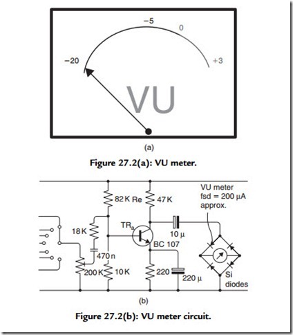
A standard VU meter is illustrated in Figure 27.2(a). The VU is a unit intended to express the level of a complex wave in terms of decibels above or below a reference volume, it implies a complex wave—a program waveform with high peaks. A 0 VU reference level therefore refers to a complex-wave power reading on a standard VU meter. A circuit for driving a moving coil VU meter is given in Figure 27.2(b). Note that the rectifiers
and meter are fed from the collector of TRa, which is a current source in parallel with Re. Because Re is a high value in comparison with the emitter load of TRa the voltage gain during the part of the input cycle when the rectifier diodes are not in conduction is very large. This alleviates most of the problem of the Si diodes’ offset voltage. From the circuit it is clear that a VU meter is an indicator of the average power of a waveform; it therefore accurately represents the apparent loudness of a signal because the ear too mathematically integrates audio waveforms with respect to time. However, because of this, the VU is not a peak-reading instrument. A failure to appreciate this, and on a practical level this means allowing the meter needle to swing into the red section on transients, means that the mixer is operating with inadequate system headroom. This characteristic has led the VU to be regarded with suspicion in some organizations.
To some extent, this is unjustified because the VU may be used to monitor peak levels, provided the action of the device is properly understood. The usual convention is to assume that the peaks of the complex wave will be 10 to 14 dB higher than the peak value of a sine wave adjusted to give the same reference reading on the VU meter. In other words, if a music or speech signal is adjusted to give a reading of 0 VU on a VU meter, the system must have at least 14 dB headroom—over the level of a sine wave adjusted to give the same reading—if the system is not to clip the program audio signal. In operation, the meter needles should swing only very occasionally above the 0 VU reference level on complex program.
The PPM Meter
Whereas the VU meter reflects the perceptual mechanism of the human hearing system, and thereby indicates the loudness of a signal, the PPM is designed to indicate the value of peaks of an audio waveform. It has its own powerful champions, notably the BBC and other European broadcasting institutions. The PPM is suited to applications in which the balance engineer is setting levels to optimize a signal level to suit the dynamic range available from a transmission (or recording) channel. Hence its adoption by broadcasters who are under statutory regulation to control the depth of their modulation and therefore fastidiously to control their maximum signal peaks. In this type of application, the balance engineer does not need to know the “loudness” of the signal, but rather needs to know the maximum excursion (the peak value) of the signal.
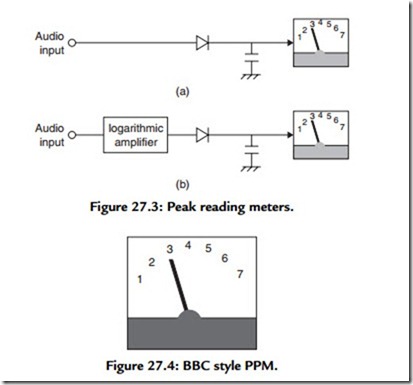
It is actually not difficult to achieve a peak reading instrument. The normal approach is a meter driven by a buffered version of a voltage stored on a capacitor, itself supplied by a rectified version of the signal to be measured [see Figure 27.3(a)]. In fact, the main limitation of this approach lies with the ballistics of the meter itself, which, unless standardized, leads to different readings. The PPM standard demands a defined and consistent physical response time of the meter movement. Unfortunately, the simple arrangement is actually unsuitable as a volume monitor due to the highly variable nature of the peak to average ratio of real-world audio waveforms, a ratio known as crest factor. This enormous ratio causes the meter needle to flail about to such an extent that it is difficult to interpret anything meaningful at all! For this reason, to the simple arrangement illustrated in Figure 27.3(a), a logarithmic amplifier is appended as shown at Figure 27.3(b). This effectively compresses the dynamic range of the signal prior to its display;
a modification that (together with a controlled decay time constant) enhances the PPM’s readability greatly—albeit at the expense of considerable complexity.
The peak program meter of the type used by the BBC is illustrated in Figure 27.4. Note the scale marked 1 to 7, with each increment representing 4 dB (except between 1 and 2, which represents 6 dB). This constant deflection per decade is realized by the logarithmic amplifier. The line-up tone is set to PPM4 and signals are balanced so that peaks reach PPM6, which is 8 dB above the reference level. (The BBC practice is that the peak studio level is 8 dB above the alignment level.) BBC research has shown that the true peaks are actually about 3 dB higher than those indicated on a BBC PPM and that operator errors cause the signal to swing occasionally 3 dB above the indicated permitted maximum, that is, a total of 14 dB above alignment level.
PPM Dynamic Performance
PPM
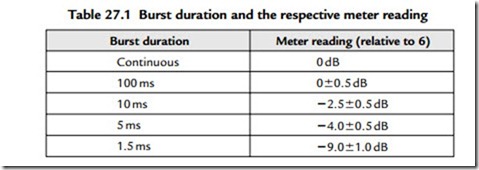
In BS55428 Part 9, the PPM is stated as requiring, “an integration time of 12 ms and a decay time of 2.8 s for a decay from 7 to 1 on the scale.” This isn’t entirely straightforward to understand. However, an earlier standard (British Standard BS4297:1968) defined the rise time of a BBC style PPM in terms of reading relative to 5-kHz tone-burst durations such that, for a steady tone adjusted to read scale 6, bursts of various values should be within the limits given here:
This definition has the merit of being testable.
VU Meter
The VU meter is essentially a milliammeter with a 200-mA FSD fed from a full-wave rectifier installed within the case with a series resistor chosen such that the application of a sine wave of 1.228 V RMS (i.e., 4 dB above that required to give 1 mW in 600 R) causes a deflection of 0 VU. Technically, this makes a VU an rms reading volt meter. Of course, for a sine wave the relationship between peak and rms value is known (3 dB or 1/V2), but no simple relationship exists between rms and pk for real-world audio signals.
In frequency response terms, the response of the VU is essentially flat (0.2 dB limits) between 35 Hz and 10 kHz. The dynamic characteristics are such that when a sudden sine wave type signal is applied, sufficient to give a deflection at the 0 VU point, the pointer shall reach the required value within 0.3 s and shall not overshoot by more than 1.5% (0.15 dB).
Opto-Electronic Level Indication
Electronic level indicators range from professional bargraph displays, which are designed to mimic VU or PPM alignments and ballistics, through the various peak-reading displays common on consumer and prosumer goods (often bewilderingly calibrated), to simple peak-indicating LEDs. The latter, can actually work surprisingly well—and actually facilitate a degree of precision alignment, which belies their extreme simplicity.
In fact, the difference between monitoring using VUs and PPMs is not as clear cut as stated. Really, both meters reflect a difference in emphasis: the VU meter indicates loudness—leaving the operator to allow for peaks based on the known, probabilistic nature of real audio signals. The PPM, however, indicates peak, leaving it to the operator to base decisions of apparent level on the known stochastic nature of audio waveforms.
However, the latter presents a complication because, although the PPM may be used to judge level, it does take experience. This is because the crest factor of some types of program material differs markedly from others, especially when different levels of compression are used between different contributions. To allow for this, institutions that employ the PPM apply ad hoc rules to ensure continuity of level between contributions and/or program segments. For instance, it is BBC practice to balance different program material to peak at different levels on a standard PPM.
Despite its powerful European opponents, a standard VU meter combined with a peak- sensing LED is very hard to beat as a monitoring device because it both indicates volume and, by default, average crest factor. Any waveforms that have unusually high peak-to- average ratio are indicated by the illumination of the peak LED. Unfortunately, PPMs do not indicate loudness, and their widespread adoption in broadcast accounts for the many uncomfortable level mismatches between different contributions, especially between programs and adverts.
Polar CRT Displays
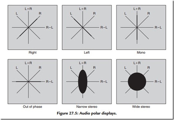
One very fast indicator of changing electrical signals is a cathode ray tube (CRT). With this in mind, there has, in recent years, been a movement to use CRTs as a form of fast audio monitoring, not as in an oscilloscope, with an internal timebase, but as a polar, or XY display. The two-dimensional polar display has a particular advantage over a classic, one-dimensional device like a VU or PPM in that it can be made to display left and right signals at the same time. This is particularly useful because, in so doing, it permits the engineer to view the degree to which the left and right signals are correlated; which is to say the degree to which a stereo signal contains in-phase, mono components and the degree to which it contains out-of-phase or stereo components.
In the polar display, the Y plates inside the oscilloscope are driven with a signal that is the sum of the left and right input signal (suitably amplified). The X plates are driven with a signal derived from the stereo difference signal (R – L), as shown in Figure 27.5. Note that the left signal will create a single moving line along the diagonal L axis as shown. The right signal clearly does the same thing along the R axis. A mono (L = R)
signal will create a single vertical line, and an out-of-phase mono signal will produce a horizontal line. A stereo signal produces a woolly ball centered on the origin; its vertical extent is governed by the degree of L/R correlation and its horizontal extent is governed by L/R decorrelation. And herein lies the polar display’s particular power, that it can be used to assess the character of a stereo signal, alerting the engineer to possible transmission or recording problems, as illustrated in Figure 27.5.
One disadvantage of the polar display methodology is that, in the absence of modulation, the cathode ray will remain undeviated and a bright spot will appear at the center of the display, gradually burning a hole on the phosphor! To avoid this, commercial polar displays incorporate cathode modulation (k mod) so that, if the signal goes below a certain value, the cathode is biased until the anode current cuts off, extinguishing the beam.
