TORQUE
The torque required to operate the driven machine at every moment between the initial breakaway and the final shutdown is important in determining the motor characteristics. The various torques associated with synchronous motors are termed starting torque, running torque, pull-in torque, and pull-out torque.
Starting Torque
The starting, or breakaway, torque required by the driven machine may be as low as 10 percent, as in the case of centrifugal pumps, and as high as 225 or 250 percent of full-load torque as in the case of loaded reciprocating two-cylinder compressors.
The starting torque of a synchronous motor is the torque, or turning effort (usually measured in pound-feet or gram centimeters), which the motor develops when full voltage is applied to the armature winding.
The synchronous motor, in itself, has very little starting torque. With modern motors, however, almost any reasonable torque can be obtained by proper design of the damper windings (also called squirrel-cage and amortisseur windings). The different values of starting torque are usually obtained by changes in the resistance and size of the damper windings. As a general rule, the starting inrush of current increases as the starting torque is increased.
Running Torque
The running torque is determined by the horsepower and speed of the driven machine, and at any given point, the torque in pound-feet is:
The peak horsepower determines the maximum torque required by the driven machine. The motor must have a breakdown or a maximum running torque in excess of this figure in order to avoid stalling. Certain driven machines, like reciprocating compressors, have load torques which pulsate periodically.
To prevent excessive pulsation in the line current of the motor, proper flywheel effect (WR2 ) must be provided, either in the motor or in the driven machine. In the case of synchronous motors, the flywheel effect must be made such that the natural frequency of the motor does not approximate the frequency of any impulses in the load torque. Natural frequency in cycles per minute is:
where,
W R 2 is the weight in lbs. x (radius of gyration in ft.)2 (motor and load),
r/min is the speed of motor in revolutions per minute,
f is the line frequency,
Pr is the synchronizing power of motor in kilowatts per electrical radian.
fr is natural frequency in cycles per minute.
Pull-In Torque
When a synchronous motor has been started as an induction motor, it will run at from 2 to 5 percent below synchronous speed until the excitation is applied, at which time the rotor will pull into step. The amount of torque or load at which the motor will pull into step is called the pull-in torque. Synchronous motors are usually designed for a definite application. The designer should know the nature of the load which the motor is required to start so that he can design the motor for the necessary starting and pull- in torque.
Pull-Out Torque
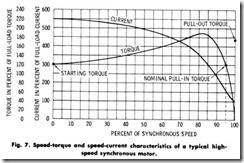
When a synchronous motor is running in synchronism with no load, the individual field poles of the rotor have a fixed position with respect to the rotating magnetic field of the armature. When a mechanical load or resisting torque is applied to the shaft, the motor develops a torque to balance the requirements of the load torque. The increased torque requirement is produced by a backward shift or lag in the position of the field poles with respect to the rotating magnetic field. However, the rotor will maintain its synchronous speed. When, because of the increased torque requirement, the field poles have shifted backward approximately half the distance between adjacent poles, the motor is developing its maximum torque. Any further increase will cause the motor to pull out of step and stop. The maximum torque which the motor will develop without pulling out of step is called the pull-out torque. The speed-torque and speed-current characteristics of a typical synchronous motor are shown in Fig. 7.
POWER FACTOR
The power in watts delivered through a single-phase ac circuit is the product of the current, voltage, and power factor, and is written as:
In a three-phase ac circuit, the power in watts is written as:
Since W represents the true power and the product EI the apparent power, the power factor (cos Ø) may be defined as the ratio of the true and apparent power delivered through the circuit.
The fact that a synchronous motor always operates at a leading power factor or unity (100 %), whereas an induction motor operates at a lagging power factor and receives its excitation from the line, has been made use of for power-factor improvements. Employment of synchro nous motors, therefore, helps to improve the plant operating power factor. In many cases, synchronous motors also cost less and have higher efficiencies than corresponding induction motors. This is partic ularly true for low-speed synchronous motors.
Many rate schedules incorporate a power-factor clause, adjusting the rate according to power factor; others involve a penalty or bonus if the power factor is, for example, below 90-percent or above 90-percent lagging.
A synchronous motor operating at full load and its rated excitation delivers to the power system a leading kV A equal to:
It should be noted that, at partial loads and rated excitation, more leading kVA is supplied. The curves in Fig. 5 approximate the leading reactive kV A for synchronous motors at four different power-factor ratings and at varying load conditions, based on maintaining full-load rating power excitation at all loads. Thus, at three-quarter load, for example, a (74.6 kW) 80-percent power factor synchronous motor driving an air compressor supplies a leading reactive kV A equal to approximately 66 percent of its horsepower rating, or 66 reactive kVA. See Fig. 5.
The unity power factor synchronous motor, whose curves are shown in Fig. 5, supplies a leading reactive kVA only at part load. At full load, however, although providing no leading reactive kVA, it still improves the power factor by adding to the kilowatt load without increasing the reactive- kVA load. A unity power factor synchronous motor costs less than a leading power factor synchronous motor of the same horsepower and rating because less material is used in its windings and magnetic parts. Highest efficiency is also obtained with a unity power factor synchronous motor, but when considerable power factor improvement is required, leading power factor synchronous motors are generally preferable.
A simple approximate rule for estimating the leading kVA require ment for power factor correction is as follows: Each horsepower of an 80-percent power factor synchronous motor, operating at full load and rated excitation, will supply the lagging reactive kV A for a ( 1 kW) high-speed induction motor. Thus, a (55.95 kW) 80-percent power factor synchronous motor will correct to unity power factor approxi mately (74.6 kW) in high speed induction motors.


