Speed of action
A mechanical switch operating with mains AC will normally have an opening or closing time that is short compared with the time of a cycle. This does not apply to switches that are used for higher frequencies, so that the rating of switch contacts for such signals is closer to the DC rating than to the AC (mains) rating. If switching has to be carried out in very short times, then semiconductor switching devices need to be used. These are dealt with later in this chapter, although more as adjuncts to mechanical switches than as a subject in their own right. Since switching speed is inevitably slow in comparison to the time of one cycle of wave, it is less relevant to the specification of switches for signal frequencies, and for low-power signals the time of switching is usually dependent on the action of the operator. A wafer switch, for example, will change connections in a time that is determined completely by how fast the operator turns the switch knob. For audio work, switches with a snap-over action are often used, but for all sorts of work where conditions are critical in terms of speed and noise-free operation the combination of a mechanical switch with a semi- conductor switch is now more common.
Capacitance
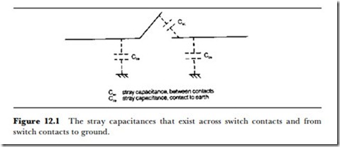
Two figures for capacitance are significant in a switch intended for use with signals: the stray capacitance to ground and the capacitance across the open contacts. Taking the latter first, the open-circuit capacitance (Figure 12.1) determines to a large extent the efficacy of the switch in terms of open and closed circuit impedance. The figure, unfortunately, is seldom quoted but will be in the range of 10-20 pF for the common types of signal switches. This will cause a significant amount of signal to appear on ‘open’
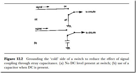
contacts, particularly for high-frequency or fast-rising signals, unless the switches are operated in circuits of low impedance. For this reason, a simple open-and-close type of switching arrangement is seldom suitable for high-frequency signal switching, and the switch should ensure that no unwanted signal is coupled across by grounding the ‘cold’ side of the switch when the switch is off. Obviously if a DC bias exists on the cold side of the switch contacts, the grounding will be done through a capacitor. Figure 12.2 illustrates this principle applied to a single-way switch.
The type of switch mechanism very greatly affects the amount of capaci- tance that exists between the contacts. The contacts of a wafer switch lie in the same plane, with only a very tiny area of contact conductor parallel to any other conductor, so they have very low capacitance across the contacts. This is a major reason for the continued popularity of this switch type, which has remained almost unchanged (apart from improvements in materials) for some 60 years. The type of switch in which open contacts lie parallel to each other is the worst, from the point of view of open-contact capacitance, although if the open contacts are reasonably far apart, the amount of capacitance between them can be as low as can be achieved in a wafer design. Since speed of action is seldom an important factor for the mechanical switch, a comparatively large distance between open contacts can be specified in push-button and keyboard switches.
Another important aspect of capacitance in signal-carrying switches is the stray capacitance between contacts that carry different signals. If a switch is used to carry several signal channels, then capacitance between contacts can lead to signal crosstalk. If impedance levels and signal levels are both low, the amount of such crosstalk may be insignificant, but in the worst- case example of a high-level signal on one channel and a low-level signal on another, with comparatively high impedance, the amount of crosstalk would become intolerable. Multi-channel switching of this type is best handled by ganged assemblies in which the channels can be kept physically well separated. Once again, the familiar wafer switch copes best with this requirement if one wafer is used for each channel, with grounded screens placed between the wafers.
Stray capacitance to ground is, by contrast, much less of a hazard unless the switch is being used in a high-impedance circuit. By their nature, most switches are mounted on conducting panels, so that stray capacitance to ground is always significant, but since this stray capacitance has little or no effect on switching performance it can be treated like any other stray capacitance to ground in the circuit. Stray capacitance of this type becomes a problem only if the local ground happens to be the hand of the operator, which can occur when a signal-carrying switch is mounted on a non-con- ducting panel. This will have the effect of making the stray capacitance to ground much larger when the switch is being operated than at other times, and is the same effect as the hand-capacity problem that haunted amateur radio builders many years ago. This manifested itself as a change of tuned frequency as the user’s hand approached or was taken away from the tuning control.
Once again, the problem may be negligible: it is only likely to cause difficul- ties if the switch happens to be part of a tuned circuit whose frequency can be changed by the alteration in capacitance to ground. This problem can also be solved by the use of a wafer switch with a grounding screen. In general, switches should not be mounted on insulating panels for any application in which variation of capacitance is undesirable.
All these remarks on stray capacitance underline the importance of good circuit design, in which switches are never placed in high-impedance circuits. Except for the most demanding of waveforms, with very fast rise and fall times, switch capacitance is never a problem when impedance levels are low. At high impedance levels, the switch capacitance to ground is just one of the stray capacitances to ground, and presents no special problems unless the capacitance varies. The main problem for higher impedance circuits is capacitance between switch contacts, and this can be reduced to very small amounts, as we have seen. The usual and least avoidable type of high-impedance circuit is the tuned circuit in which a switch is used to change inductors, capacitors or the complete LC tuned circuit for an oscillator. In this case, the stray capacitance across contacts has an effect that is constant, and which can be dealt with by any form of fine-tuning adjustment.

