Capacitor Time Limit Relay
Assume that a capacitor is charged by connecting it momentarily across a DC line, and then the capacitor direct current is discharged through a relay coil. The
current induced in the coil will decay slowly, depending on the relative values of capacitance, inductance, and resistance in the discharge circuit.
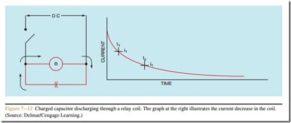
If a relay coil and a, capacitor are connected parallel to a DC line (Figure 7– 12), the capacitor is charged to the value of the line voltage and a current appears in
the coil. If the coil and capacitor combination is now removed from the line, the current in the coil will start to decrease along the curve shown in Figure 7 – 12.
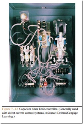
If the relay is adjusted so that the armature is released at current i1, a time delay of t1 is obtained. The time delay can be increased to a value of t 2 by adjusting the relay so that the armature will not be released until the current is reduced to a value of i 2. Figure 7 – 13 shows a relay used for this type of time control.
A potentiometer is used as an adjustable resistor to vary the time. This resistance-capacitance (RC) theory is used in industrial electronic and solid-state controls also. This timer is highly accurate and is used in motor acceleration control and in many industrial processes.

