STARTING AND REVERSING
In order to prevent damage to a motor when starting, it is necessary to use a variable starting resistance (starting rheostat) in series with the armature. The need for such a starting resistance becomes apparent if it is remembered that when a motor whose armature is at rest is connected directly to the line, the initial inrush of current will be limited only by the resistance and self -inductance of the armature and series-field winding (when used). Since these resistances are very small, this current would reach a value several times the normal full-load current and, as a consequence, the motor would be severly damaged if not completely burned out. Thus, the need for a current-limiting device becomes apparent.
This current-limiting device is known as the starting rheostat, and consists of a number of resistance steps in which a step is cut out each time the current falls to a predetermined value. The starting resistance is generally designed so that the motor will start a full load with a starting current not to exceed 150% of the full-load current.
To reverse the direction of rotation in any de motor, the connections to the armature terminals alone, or the connections to the field winding (or windings) alone, must be reversed. If both (or all) are reversed, the direction remains unchanged. The foregoing will be apparent from a study of the equation for the torque, which is:
A negative torque (which will result in a reversal of direction) will be obtained by changing the polarity of either the current or the flux. If both are changed, the result will be a positive or unchanged torque,
since a negative value multiplied by another negative value will give a positive product.
CONTROLLERS
De motor controllers are divided into two principal classes, depend ing on their method of operation:
1. Manual controllers,
2. Magnetic controllers.
In the former, the acceleration of the motor armature is performed entirely by manipulation of the rheostat arm (or arms) by hand, whereas in the latter, the starter is moved into position by the magnetic action of a coil (or coils) which are usually energized by the closing of a light auxiliary switch, or switches, usually called starting buttons.
Manual Controllers
Manual controllers are supplied in three principal forms, termed as:
(a) faceplate controllers, (b) multiswitch controllers, and (c) drum controllers.
Faceplate Controllers-Faceplate controllers are divided into various classifications, depending on their duty, as follows:
1 . For starting duty only,
|
2. For |
starting and regulating |
duty and for providing the speed increases of from one to four times full-speed value by field control only,
|
||
|
|
|
|
, |
|
3. For starting and regulating duty providing a minimum of 50% speed reduction by armature control only,
4. For starting and regulating duty providing a 50% speed reduction by armature control and a 25% increase by field control.
From speed regulation by armature control, two classes of service are obtained-constant torque and varying torque. Constant-torque appli cations include machine tools, plunger-type pumps, and similar loads where the horsepower output of the motor decreases directly with the motor speed, while the torque remains constant. Varying-torque appli cations include blowers, centrifugal pumps, and similar loads where the torque varies approximately as the square of the motor speed.
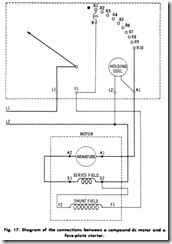
Operation-Fig. 17 shows the wiring diagram of a Class-1 (for starting duty only) faceplate controller. The operation is as follows:
Connection is made from one of the line wires to a contact arm whose function it is to carry the current over a series of stationary contact buttons provided with graduated resistance steps to the motor winding. When the contact arm is moved toward the right, the first connection serves to put the shunt-field circuit directly across the line. When the contact arm is moved over all the way to the right (which is the running position), it makes contact with a magnet coil (variously termed holding coil or no- voltage release) whose purpose it is to hold the contact arm in position during normal conditions of the circuit. If the voltage fails, the magnet coil will be de-energized and spring action will carry the contact arm back to its original position. This action prevents the motor from being connected directly across the line when voltage is restored to the line.
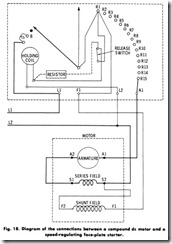
Faceplate controllers of Class 2 (designed for both starting and speed-regulating duty, Fig. 18) combine the functions of starting by means of armature resistance, and speed regulation by means of field-circuit resistance, Thus, the rheostats have a compound contact arm, one for starting and one for regulating speed. The starting arm is spring-retained. In starting, the starting arm is moved to the running position (by the regulating arm), where it is held by the low-voltage release magnet, while the regulating arm is carried back to the correct point for the desired speed.
Faceplate controllers of Class 3 (designed for speed regulation below normal speed by armature resistance only) are very similar to rheostats of Class 1, except that all the starting buttons or segments must be dimensioned to carry the full-load current continuously. In this type of rheostat, the no-voltage release is arranged to hold the movable contact arm at any desired point. This is accomplished by equipping the contact arm with a pawl, and the magnet operates to hold the contact arm in any operating position.
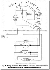
Class 4 faceplate controllers are designed to reduce the speed of the motor 50%, when fully loaded at normal speed, by inserting resistance in the armature circuits, and to increase the speed 25% by regulating the resistance in the field circuit. A typical wiring diagram for a controller of this class is shown in Fig. 19. These controllers are designed in two types, one having a small number of field-regulating steps, and the other a large number.
Controllers equipped with a relatively small number of buttons (resistance steps) are used for standard constant-speed motors where it is desired to increase the speed by 25o/o by weakening the field current. A large number of buttons (resistance steps) signifies starting rheostats where a wide range of speed is desired through field-control regulation.
Multiple Switch Controllers-These are designed with a series of switches which must be closed manually in a left-to-right sequence, and with a hand-over-hand motion. This arrangement provides a certain element of safety because of the time element required, compared to the manual starter where the operator often gives the controller rough treatment by cutting out the resistance too rapidly.
Successive portions of the starting resistance are cut out as each switch is closed. The switches are so mechanically interlocked as to prevent closing in any other but the proper sequence. Each successive switch mechanically locks the preceding one. The last switch is locked in by a catch which is held by a low-voltage protection magnet. Ratings run to 150 hp ( 111.9 kW) and are especially adaptable to large-motor manual starting because of the time element introduced by the hand over-hand closing procedure necessary , Multiple-switch units are for starting duty only, without dynamic braking, and for nonreversing service of either shunt, series, or compound motors.
Drum Controllers-These are used for starting and control of ad justable-speed motors having speed ranges of four-to-one or less . Drum controllers are used for control to both ac and de motors in various services, such as in the machine-tool industry, hoisting work, for control of trolley-car motors, railroad motors, etc. When used in connection with de motors, drum controllers are available for both reversing and nonreversing service and for armature-starting, field regulating applications.
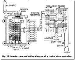
With reference to Fig. 20, the drum controller consists essentially of a drum cylinder insulated from its central shaft to which the operating handle is attached. To facilitate the operation, copper segments are attached to the drum. These segments are connected to and insulated from one another, as shown in the diagram of connections.
A series of stationary fingers is arranged to make contact with the segments. These fingers are insulated from one another but intercon nected to the starting resistance and the motor circuit. The drum assembly has a notched wheel keyed to the central shaft, the function of which is to indicate to the operator when complete contact at each step is made . When controller is moved forward one notch, the fingers are in position 1 . The current then flows from L1 through all the series resistance to L2 , and the motor starts rotating. When the handle is moved further, the resistance is gradually being cut out of the armature circuit and inserted into the field circuit. Finally, when the handle is turned to notch 4, all of the resistance has been transferred from the armature to the field circuit, and the motor is running at full speed.
Drum control units may be obtained with dynamic braking resistors and, in some instances, a magnetic contactor. A protective panel can also be provided to obtain overload and low-voltage protection. Drum controllers are generally provided with the reset contact that requires the drum to be returner to the OFF position before the protective panel can be reset after the overload or voltage failure.
Overload protection is usually obtained by instantaneous thermal relays which have an inverse time characteristic for normal overloads, but which trip instantaneously on abnormal overloads (about four times the normal load or more). Rest can be manual (after returning controller to OFF) or can be made automatic.
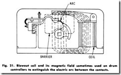
The function of the blow-out magnet sometimes used on drum controllers is to extinguish the electric arc formed as the contacts open, thus preventing the fingers and corresponding contacts from damage. This extinguishing effect is provided by means of a magnetic blow-out coil, which is shown in Fig. 21 .
An asbestos plate is hinged to the core of the blow-out coil and extends the full length of the drum, and from it arc barriers project down between the fingers. The current through the blow-out coil sets up a strong magnetic flux which passes across the contacts. As the contact opens, the current forms an electric arc, which is deflected upward or downward, depending on the direction of the current in the arc, The arc, in deflecting, will strike the asbestos barrier above or below the finger and will draw out to such an extent that it will be dissipated.
In other controllers, the magnet blow-out coil is of a long narrow shape surrounding the pole piece and carried just over the line of the contact fingers. In all cases, however, the winding of the blow-out coil is connected in series with the armature of the motor, so that whatever current passes through the blow-out coil provides the necessary mag netic flux, which is approximately proportional to the amount of current supplied to the motor. The blow-out coil is made of copper wire or copper bars, the size and turns being determined by the motor current in each instance.
