EXCITATION
AC Excitation Systems
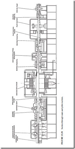
Figure 13.38 illustrates a typical ac excitation scheme. It shows the shaft-mounted main and pilot exciters together with their brush gear. Permanent-magnet pilot exciters are used to minimize dependency on external power supplies. The pilot exciter provides the excitation power for the automatic voltage regulator (AVR) control equipment. A 660-MW plant has a salient-pole pilot exciter with ratings near 100 kW. The main and pilot exciters are cooled by air. Shaft-mounted fans are used to provide the cooling. The performance is monitored by measuring the temperature at the inlet and outlet of the cooling system.
Exciter Transient Performance
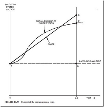
The ceiling requirements for exciters are considerably higher than for rated full-load con- ditions. The transient performance of an exciter is given by
In a typical exciter, the output voltage needs to be increased from 100 to 200 percent within 3.5 s. Figure 13.39 illustrates the average rate of increase of excitation open-circuit voltage.
The Pilot Exciter
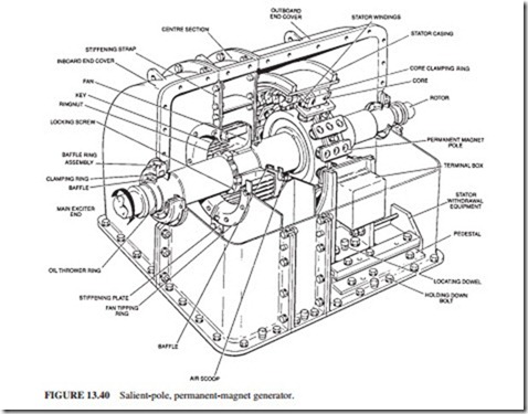
The permanent-magnet generator (PMG) pilot exciters used for 660-MW units are salient-pole design (Fig. 13.40). This design provides a constant voltage supply to the thyristor converter
and AVR control circuits. A high-energy material like Alcomax is used for the permanent- magnet poles. The poles are bolted to a steel hub and held in place by pole shoes. A nonmag- netic steel is used for the bolts to prevent the formation of a magnetic shunt. The pole shoes are skewed in some designs to improve the waveform of the output voltage and reduce electrical noise. The stator windings are arranged in a two-layer design. The stator conductors are insu- lated with polyester enamel. The coil insulation is a class F epoxy glass material.
The Main Exciter
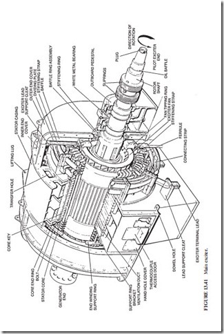
The main ac exciter has normally four or six poles (Fig. 13.41).
Exciter Performance Testing
The manufacturer of the exciters is required to perform these tests: open- and short-circuits, overspeed balancing, and high-voltage.
Pilot Exciter Protections
The pilot exciter delivers its full current during field forcing. Modern AVRs have a time/current limiter. It allows the pilot exciter to deliver maximum current during a deter- mined interval. The current is brought back to a normal value following this interval. The main exciter, like the pilot exciter, has a considerably higher margin than required. It has a
3.3-kV winding insulation despite having a working voltage of 500 V. The voltage ceiling of the main exciter is 1000 V. Its rated current is much lower than the maximum current.
Brushless Excitation Systems
Most modern gas turbines use brushless excitation systems. The rotating diodes are arranged as a three-phase bridge. The bridge arm consists of two diodes in series. If one of them fails (due to a short circuit), the second diode will continue to operate. Thus, the bridge continues to operate normally. If both diodes fail in the same arm, the fault is detected by a monitor- ing circuit which trips the machine. Essential measurements such as ground fault indication, field current, and voltage are taken by telemetry or instrument slip rings.
The Rotating Armature Main Exciter
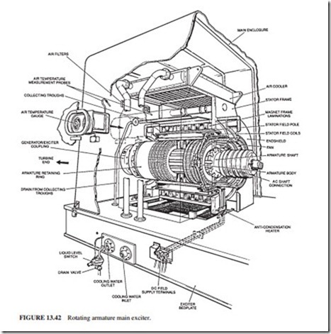
Brushless machines require less maintenance than conventional ones. They also do not have sliding or rubbing electrical contacts that cause sparking and carbon dust. The main exciter is a three-phase rotating armature ac generator. The dc field is in the stator, and the ac wind- ing is on the rotor. A typical rotating armature main exciter is illustrated in Fig. 13.42.
The exciter armature is made of low-loss steel laminations. The laminations are shrunk onto a shaft forged from annealed carbon steel. Cooling air enters axial slots along the rotor
body. The rotor conductors are made of braided strips in parallel. They are radially trans- posed to reduce eddy current losses.
The rotating rectifier of a 660-MW generator is illustrated in Fig. 13.43. It is mounted on the outboard of the main ac exciter. The three-phase ac power is supplied from the main exciter to the silicon diode rectifier by axial conductors taken along the surface of the shaft. A steel retaining ring contains the components of the rectifier against centrifugal forces. The retaining ring is shrunk on the outside of the hub.
Related posts:
Incoming search terms:
- components of excitation system
- generator components auxiliaries and excitation
- component of excitation system
- various componemt of an excitation system
- parts of an excitation system
- hardware transient exciter
- exciters of a generator
- excitation system compenants
- elements if an excitation system
- conponent of excitation system
- components of exciter in AVR
- components of excitation systems
- what is main and pilot exciter

