12.1. INTRODUCTION
Besides electromagnetic, mechanical and thermal designs are equally important.
Thermal modeling of an electric machine is in fact more nonlinear than electromagnetic modeling. Any electric machine design is highly thermally constrained.
The heat transfer in an induction motor depends on the level and location of losses, machine geometry, and the method of cooling.
Electric machines work in environments with temperatures varied, say from –200C to 500C, or from 200 to 1000 in special applications.
The thermal design should make sure that the motor windings temperatures do not exceed the limit for the pertinent insulation class, in the worst situation. Heat removal and the temperature distribution within the induction motor are the two major objectives of thermal design. Finding the highest winding temperature spots is crucial to insulation (and machine) working life.
The maximum winding temperatures in relation to insulation classes shown in Table 12.1.
Table 12.1. Insulation classes
|
Insulation class |
Typical winding temperature limit [0C] |
|
Class A |
105 |
|
Class B |
130 |
|
Class F |
155 |
|
Class H |
180 |
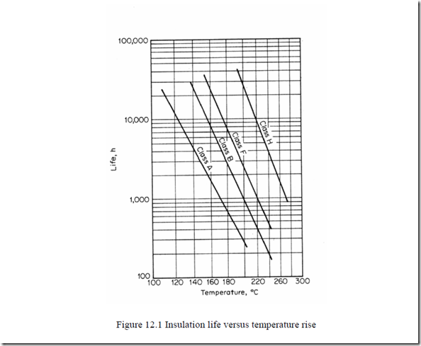
Practice has shown that increasing the winding temperature over the insulation class limit reduces the insulation life L versus its value L0 at the insulation class temperature (Figure 12.1).
LogL ≈ a + b (12.1)
T
It is very important to set the maximum winding temperature as a design constraint. The highest temperature spot is usually located in the stator end connections. The rotor cage bars experience a larger temperature, but they are not, in general, insulated from the rotor core. If they are, the maximum (insulation class dependent) rotor cage temperature also has to be observed.
The thermal modeling depends essentially on the cooling approach.
12.2. SOME AIR COOLING METHODS FOR IMs
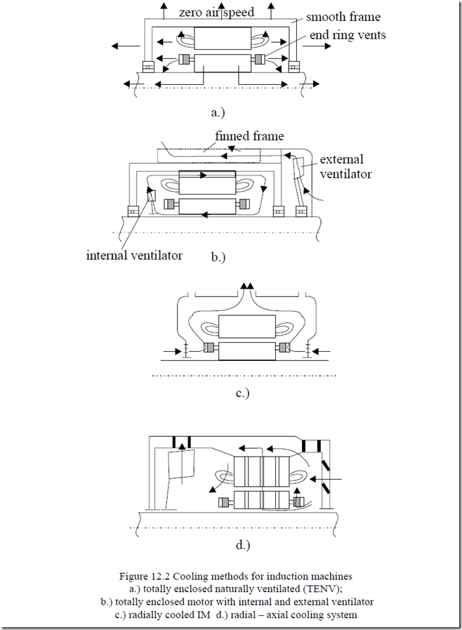
For induction motors, there are four main classes of cooling systems
• Totally enclosed design with natural (zero air speed) ventilation (TENV)
• Drip-proof axial internal cooling
• Drip-proof radial internal cooling
• Drip-proof radial-axial cooling
In general, fan air-cooling is typical for induction motors. Only for very large powers is a second heat exchange medium (forced air or liquid) used in the stator to transfer the heat to the ambient.
TENV induction motors are typical for special servos to be mounted on machine tools etc., where limited space is available. It is also common for some static power converter-fed IMs, that operate at large loads for extended periods of time at low speeds to have an external ventilator running at constant speed to maintain high cooling in all conditions.
The totally enclosed motor cooling system with external ventilator only (Figure 12.2b) has been extended lately to hundreds of kW by using finned stator frames.
Radial and radial-axial cooling systems (Figure 12.2c, d) are in favor for medium and large powers.
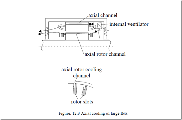
However, axial cooling with internal ventilator and rotor, stator axial channels in the core, and special rotor slots seem to gain ground for very large power as it allows lower rotor diameter and, finally, greater efficiency is obtained, especially with two pole motors (Figure 12.3). [2]
The rotor slots are provided with axial channels to facilitate a kind of direct cooling.
axial channel
The rather complex (anisotropic) structure of the IM for all cooling systems presented in Figures 12.2 and 12.3 suggests that the thermal modeling has to be rather difficult to build.
There are thermal circuit models and distributed (FEM) models. Thermal circuit models are similar to electric circuits and they may be used both for thermal steady state and transients. They are less precise but easy to handle and require a smaller computation effort. In contrast, distributed (FEM) models are more precise but require large amounts of computation time.
We will define first the elements of thermal circuits based on the three basic methods of heat transfer: conduction, convection and radiation.
12.3. CONDUCTION HEAT TRANSFER
Heat transfer is related to thermal energy flow from a heat source to a heat sink.
In electric (induction) machines, the thermal energy flows from the windings in slots to laminated core teeth through the conductor insulation and slot line insulation.
On the other hand, part of the thermal energy in the end-connection windings is transferred through thermal conduction through the conductors axially toward the winding part in slots. A similar heat flow through thermal conduction takes place in the rotor cage and end rings.
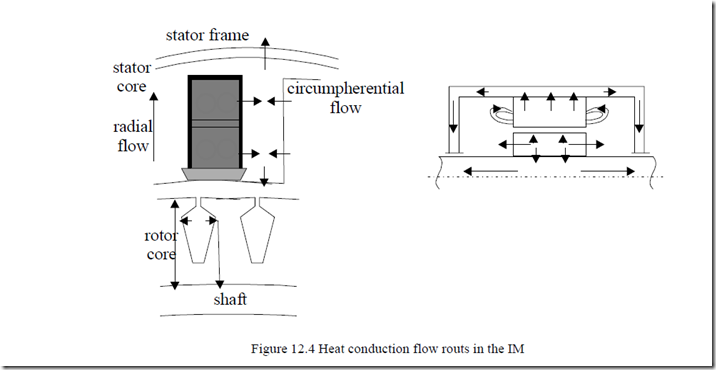
There is also thermal conduction from the stator core to the frame through the back core iron region and from rotor cage to rotor core, respectively, to shaft and axially along the shaft. Part of the conduction heat now flows through the slot insulation to core to be directed axially through the laminated core. The presence of lamination insulation layers will make the thermal conduction along the axial direction more difficult. In long stack IMs, axial temperature differentials of a few degrees (less than 100C in general), (Figure 12.4), occur.
So, to a first approximation, the axial heat flow may be neglected. Second, after accounting for conduction heat flow from windings in slots to the core teeth, the machine circumferential symmetry makes possible the neglecting of circumferential temperature variation.
So we end up with a one-dimensional temperature variation, along the radial direction. For this crude approximation defining thermal conduction, convection, and radiation, and of the equivalent circuit becomes a rather simple task.
The Fourier’s law of conduction may be written, for steady state, as
∇ −( K∆θ =) q (12.2) where q is heat generation rate per unit volume (W/m3); K is thermal conductivity (W/m, 0C) and θ is local temperature.
For one-dimensional heat conduction, Equation (12.2), with constant thermal conductivity K, becomes:
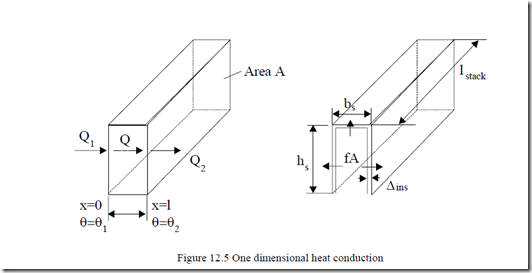
A basic heat conduction element (Figure 12.5) shows that power Q
transported along distance l of cross section A is
Q ≈ q l A⋅ ⋅ (12.4) with q, A – constant along distance l.
The thermal conduction resistance Rcon may be defined as similar to electrical resistance.
Rcon = KAl [0C/ W] (12.5)
Temperature takes the place of voltage and power (losses) replaces the electrical current.
For a short l, the Fourier’s law in differential form yields
f ≈ −K ∆∆θx ; f − heat flow density [W/m2 ] (12.6)
If the heat source is in a thin layer,
f = pcos (12.7)
A
pcos in watts is the electric power producing losses and A the cross-section area. For the heat conduction through slot insulation ∆ins (total, including all conductor insulation layers from the slot middle (Figure 12.5)), the conduction area A is
A = (2hs + b ls ) stack N ; Ns s −slots/stator (12.8)
The temperature differential between winding in slots and the core teeth ∆θCo is
∆ins (12.9)
∆θCos = pcosRcon; Rcon =
AK
In well-designed IMs, ∆Θcos < 100C with notably smaller values for small power induction motors.
The improvement of insulation materials in terms of thermal conductivity and in thickness reduction have been decisive factors in reducing the slot insulation conductor temperature differential. Thermal conductivity varies with temperature and is constant only to a first approximation. Typical values are
given in Table 12.2. The low axial thermal conductivity of the laminated cores is evident.
Table 12.2. Thermal conductivity
|
Material |
Thermal conductivity (W/m0C) |
Specific heat coefficient Cs (J/Kg/0C) |
|
Copper |
383 |
380 |
|
Aluminum Carbonsteel |
204 45 |
900 |
|
Motor grade steel |
23 |
500 |
|
Si steel lamination – Radial; – Axial |
20 – 30 2.0 |
490 |
|
Micasheet |
0.43 |
– |
|
Varnished cambric |
2.0 |
– |
|
Press board Normex |
0.13 |
– |
12.4. CONVECTION HEAT TRANSFER
Convection heat transfer takes place between the surface of a solid body (the stator frame) and a fluid (air, for example) by the movement of the fluid. The temperature of a fluid (air) in contact with a hotter solid body rises and sets a fluid circulation and thus heat transfer to the fluid occurs. The heat flow out of a body by convection is
qconv = hA∆θ (12.10) where A is the solid body area in contact with the fluid; ∆θ is the temperature differential between the solid body and bulk of the fluid, and h is the convection heat coefficient (W/m2⋅0C).
The convection heat transfer coefficient depends on the velocity of the fluid, fluid properties (viscosity, density, thermal conductivity), the solid body geometry, and orientation. For free convention (zero forced air speed and smooth solid body surface [2])
hCo ≈ 2.158(∆θ)0.25 vertical up – W/ m C( 20 )
hCo ≈ 0.496(∆θ)0.25 vertical down- W/ m C( 20 ) (12.11)
hCo ≈ 0.67(∆θ)0.25 horizontal – W/ m C( 20 )
where ∆θ is the temperature differential between the solid body and the fluid. For ∆θ = 200C (stator frame θ1 = 600C, ambient temperature θ2 = 400C) and vertical – up surface
hCo = 2.158 60( − 40)0.25 = 4.5W/(m20C)
When air is blown with a speed U along the solid surfaces, the convection heat transfer coefficient hc is
![]() hC0 ( )u = hCo (1+ K U) (12.12) with K = 1.3 for perfect air blown surface; K = 1.0 for the winding end connection surface, K = 0.8 for the active surface of rotor, K = 0.5 for the external stator frame.
hC0 ( )u = hCo (1+ K U) (12.12) with K = 1.3 for perfect air blown surface; K = 1.0 for the winding end connection surface, K = 0.8 for the active surface of rotor, K = 0.5 for the external stator frame.
|
Alternatively, |
|
|
hC ( )u =1.77 U0.250.75 W/ m( 20C for U) > 5m/s L U in m/s and L is the length of surface in m. For a closed air blowed surface – inside the machine: |
(12.13) |
|
(12.14) |
a
θair–local air heating; θa–heating (temperature) of solid surface.
In general, θair = 35 – 400C while θa varies with machine insulation class. So, in general, a < 1.
For convection heat transfer coefficient in axial channels of length, L (12.13) is to be used.
In radial cooling channels, hcc(U) does not depend on the channel’s length, but only on speed.
hcc ( )U ≈ 23.11U0.75 (W / m20C) (12.15)
12.5. HEAT TRANSFER BY RADIATION
Between two bodies at different temperatures there is a heat transfer by radiation. One body radiates heat and the other absorbs heat. Bodies which do not reflect heat, but absorb it, are called black bodies.
Energy radiated from a body with emissivity ε to black surroundings is
qrad =σε θ −θ =σε θ +θ θ +θ θ −θA( 14 42 ) A( 1 2 )( 12 22 )( 1 2 ) (12.16) σ–Boltzmann’s constant: σ = 5.67⋅10-8 W/(m2K4); ε – emissivity; for a black painted body ε = 0.9; A–radiation area.
In general, for IMs, the radiated energy is much smaller than the energy transferred by convection except for totally enclosed natural ventilation (TENV) or for class F(H) motor with very hot frame (120 to 150°C).
For the case when θ2 = 40° and θ1 = 80°C, 90°C, 100°C, ε = 0.9, hrad = 7.67, 8.01, and 8.52 W/(m2 °C).
For TENV with hCo = 4.56 W/(m2, °C) (convection) the radiation is superior to convection and thus it cannot be neglected. The total (equivalent) convection coefficient h(c+r)0 = hCo + hrad ≥ 12 W/(m2, °C).
The convection and radiation combined coefficients h(c+r)0 ≈ 14.2W/(m2, °C) for steel unsmoothed frames, h(c+r)0 = 16.7W/(m2, °C) for steel smoothed frames, h(c+r)0 = 13.3W/(m2, °C) for copper/aluminum or lacquered or impregnated copper windings. In practice, for design purposes, this value of hCo, which enters Equations (12.12 through 12.14), is, in fact, h(c+r)0, the combined convection radiation coefficient.
It is well understood that the heat transfer is three dimensional and as K, hc and hrad are not constants, the heat flow, even under thermal steady state, is a very complex problem. Before advancing to more complex aspects of heat flow, let us work out a simple example.
Example 12.1. One – dimensional simplified heat transfer
In an induction motor with pCo1 = 500 W, pCo2 = 400 W, piron = 300 W, the stator slot perimeter 2hs + bs = (2.25 + 8) mm, 36 stator slots, stack length: lstack = 0.15 m, an external frame diameter De = 0.30 m, finned area frame (4 to 1 area increase by fins), frame length 0.30m, let us calculate the winding in slots temperature and the frame temperature, if the air temperature increase around the machine is 10°C over the ambient temperature of 30°C and the slot insulation total thickness is 0.8 mm. The ventilator is used and the end connection/coil length is 0.4.
Solution
First, the temperature differential of the windings in slots has to be calculated. We assume here that all rotor heat losses crosses the airgap and it flows through the stator core toward the stator frame.
In this case, the stator winding in slot temperature differential is (12.3)
∆inspCo11− l
![]() ( lendcon) 0.8⋅10−3 ⋅500⋅0.6 = 3.83 C0
( lendcon) 0.8⋅10−3 ⋅500⋅0.6 = 3.83 C0
∆θcos = KinsN 2hs s + b lcoils stack = 2.0 0.⋅ 36⋅0.058⋅0.15
Now we consider that stator winding in slot losses, rotor cage losses, and stator core losses produce heat that flows radially through stator core by conduction without temperature differential (infinite conduction!).
Then all these losses are transferred to ambient through the motor frame through combined free convection and radiation. θcore −θair = h +qtotalA = 14.2(500⋅π⋅+0.40030⋅0.3 4/1+300⋅( ) ) = 74.758 C0
(c r 0) frame
with θair = 40°, θambient = 30°, the frame (core) temperature θcore = 40 + 74.758 = 114.758°C and the winding in slots temperature θcos = θcore + ∆θcos = 114.758 + 3.83 = 118.58°C. In such TENV induction machines, the unventilated stator winding end turns are likely to experience the highest temperature spot. However, it is not at all simple to calculate the end connection temperature distribution.
12.6. HEAT TRANSPORT (THERMAL TRANSIENTS) IN A HOMOGENOUS BODY
Although the IM is not a homogenous body, let us consider the case of a homogenous body – where temperature is the same all over.
The temperature of such a body varies in time if the heat produced inside, by losses in the induction motor, is applied at a certain point in time–as after starting the motor. The heat balance equation is
Ploss = Mct d Tdt T0 + Ah(convcond) (T − T0 )
losses
per unit heat accumulation heat transfer from the body
time in W in the body through convection, conduction, radiation
M–body mass (in Kg), ct–specific heat coefficient (J/(Kg⋅0C))
A–area of heat transfer from (to) the body h–heat transfer coefficient
Denoting by
(12.17)
|
(rad) equation (12.17) becomes |
(12.18) |
|
Ploss = Ct d T( − T0 ) + (T − T0 ) |
(12.19) |
( − )
dt R t
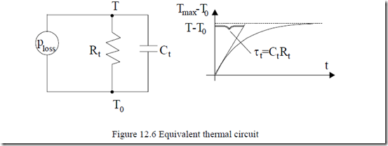
This is similar to a Rt, Ct parallel electric circuit fed from a current source Ploss with a voltage T – T0 (Figure 12.6).
For steady state, Ct does not enter Equation (12.17) and the equivalent circuit (Figure 12.6).
The solution of this electric circuit is evident.
− t − t
T = (Tmax − T0 )1− e τt + T e0 τt (12.20)
The thermal time constant τt = CtRt is very important as it limits the machine working time with a certain level of losses and given cooling conditions. Intermittent operation, however, allows for more losses (more power) for the same given maximum temperature, Tmax.
The thermal time constant increases with machine size and effectivity of the cooling system. A TENV motor is expected to have a smaller thermal time constant than a constant speed ventilator-cooled configuration.
12.7. INDUCTION MOTOR THERMAL TRANSIENTS AT STALL
The IM at stall is characterized by very large conductor losses. Core loss may be neglected by comparison. If the motor remains at stall the temperature of the windings and cores increases in time. There is a maximum winding temperature limit Tmaxcopper given by the insulation class, (1550C for class F) which should not be surpassed. This is to maintain a reasonable working life for conductor insulation. The machine is designed for lower winding temperatures at full continuous load.
To simplify the problem, let us consider two extreme cases, one with long end connection stator winding and the other a long stack and short end connections.
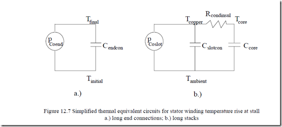
For the first case we may neglect the heat transfer by conduction to the winding in slots portion. Also, if the motor is totally enclosed, the heat transfer through free convection to the air inside the machine is rather small (because this air gets hot easily). In fact, all the heat produced in the end connection (pCoend) serves to increase end winding temperature.
∆θendcon ≈ pCoend ; Cendcon = Mendconctcopper (12.21)
∆t Cendcon
with pCoend = 1000 W, Mendcon = 1 Kg, ctcopper = 380 J/Kg/0C, the winding would heat up 115°C (from 40 to 155°C) in a time interval ∆t.
Now if the machine is already hot at, say, 1000C, ∆θendcon = 1550 – 1000 = 550C. So the time allowed to keep the machine at stall is reduced to
The equivalent thermal circuit for this oversimplified case is shown on Figure 12.7a.
On the contrary, for long stacks, only the winding losses in slots are considered. However, this time some heat accumulated in the core and the same heat is transferred through thermal conduction through insulation from slot conductors to core.
Tinitial Tambient
a.) b.)
Figure 12.7 Simplified thermal equivalent circuits for stator winding temperature rise at stall
a.) long end connections; b.) long stacks
With pCoslot = 1000 W, Mslotcopper = 1 Kg, Cslotcopper = 380 J/Kg/0C, insulation thickness 0.3 mm Kins = 6 W/m/0C, ctcore = 490 J/Kg/0C, slot height hs = 20 mm, slot width bs = 8 mm, slot number: Ns = 36, Mcore = 5 Kg, stack length lstack = 0.1 m,
Rcondinsul = (2hs + b ls ) stack N Ks ins (2 20⋅ + 8 10)⋅ −3 ⋅0.1 36 2⋅ ⋅ 8.68 10⋅ −4 0( C/ m)
(12.23)
Cslotcon = Mslotconctcopper =1⋅380 = 380J/ C0
Ccore = Mcore 0 (12.24) ctcore = 5⋅490 = 2450J/ C
The temperature rise in the copper and core versus time (solving the circuit of Figure 12.7b) is
Tcopper −Tambient = PCoslot Cslotcon +Ccore Cslotconτcon 1−e τt
(12.25)
![]() Tcore −Tambient = CslotconPCoslot+Ccore t −τt 1−e−τtt
Tcore −Tambient = CslotconPCoslot+Ccore t −τt 1−e−τtt
with τcon = CslotconRcondinsul; τ =t CCslotconslotcon +⋅CCcorecore Rcondinsul (12.26)
As expected, the copper temperature rise is larger than core temperature rise. Also, the core accumulates a good part of the winding-produced heat, so the
accumulates a good part of the winding-produced heat, so the time after which the conductor insulation temperature limit (1550C for class F) is reached at stall is larger than for the end connection windings.
The thermal time constant τt is
The second term in (12.25) dies out quickly so, in fact, only the first, linear term counts. As Ccore >> Cslotcon, the time to reach the winding insulation temperature limit is increased a few times: for Tambient = 400C and Tcopper = 1550C from (12.25).
( )∆t 400 C→1550 C = ![]() = 325.45seconds
= 325.45seconds
Consequently, longer stack motors seem advantageous if they are to be used frequently at or near stall at high currents (torques).
12.8. INTERMITTENT OPERATION
Intermittent operation with IMs occurs both in line-start constant frequency and voltage, and in variable speed drives (variable frequency and voltage).
In most line-start applications, as the voltage and frequency stay constant, the magnetization current Im is constant. Also, the rotor circuit is dominated by the rotor resistance term (Rr/S) and thus the rotor current Ir is 900 ahead of Im and the torque may be written as
![]() Te ≈ 3p L I I1 m m r = 3p L I1 m m Is2 −Im2 (12.28)
Te ≈ 3p L I I1 m m r = 3p L I1 m m Is2 −Im2 (12.28)
The torque is proportional to the rotor current, and the stator and rotor winding losses and core losses are related to torque by the expression
Pdis = pcore + pCostator + pCorotor ≈ 3R Is s2 +3R Ir r2 + pcore =
![]()
![]() Im2 + 3p L I1Tem m 2 +3Rr 3p L I1Tem m 2 + 3(ω1RL Imm m|| )2 (12.29)
Im2 + 3p L I1Tem m 2 +3Rr 3p L I1Tem m 2 + 3(ω1RL Imm m|| )2 (12.29)
= 3Rs
For fractional power (sub kW) or low speed (2p1 = 10, 12), motors Im (magnetization current) may reach 70 to 80% of rated current Isn and thus (12.29) remains a rather complicated expression of torque, with In = const. For medium and large power (and 2p1 = 2, 4, 6) IMs, in general Im < 30%Isn and Im may be neglected in (12.29), which becomes
2
Pdis ≈ (pcore )const +3(Rs + Rr ) 3p L I1Tem m (12.30)
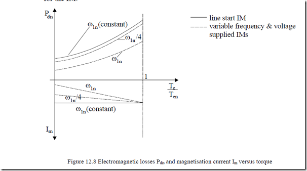
Electromagnetic losses are proportional to torque squared. For variable speed drives with IMs, the magnetization current is reduced with torque reduction to cut down (minimize) core and winding losses together.
Thus, (12.29) may be used to obtain ∂Pdis/∂Im = 0 and obtain Im(Te) and, again, from (12.29), Pdis(Te). Qualitatively for the two cases, the electromagnetic loss variation with torque is shown on Figure 12.8.
As expected, for an on-off sequence (tON, tOFF), more than rated (continuous duty) losses are acceptable during on time. Therefore, motor overloading is permitted. For constant magnetization current, however, as the losses are proportional to torque squared, the overloading is not very large but still similar to the case of PM motors [3], though magnetization losses 3RsIm2 are additional for the IM.
The duty cycle d may be defined as
ON
Complete use of the machine in intermittent operation is made if, at the end of ON time, the rated temperature of windings is reached. Evidently the average losses during ON time Pdis may surpass the rated losses Pdisn, for continuous steady state operation. By how much depends both on the tON value and on the machine equivalent thermal time constant τt.
τ =t R Ct t (12.32)
Ct–thermal capacity of winding (J/0C); Rt–thermal resistance between windings and the surroundings (0C/W). The value of τt depends on machine geometry, rated power and speed, and on the cooling system, and may run from tens of seconds to tens of minutes or even several hours.

![clip_image001[8] clip_image001[8]](http://machineryequipmentonline.com/electric-equipment/wp-content/uploads/2017/04/clip_image0018_thumb2.gif)
