Theory
In this chapter…
Digital and Binary Concepts
Gates and Logic Functions
How Transistors Work
About Electrons and Electronics
This chapter is optional. It provides an extra helping of underlying explanation and theory behind what you’ve read in the other chapters. If you’re interested in more about how computers, chips, semiconductors, and electronics work, please read on.
Digital and Binary Concepts
We’re all used to counting up to 10 on our fingers. We know that there are 10 digits, from 0 to 9, and after 9 comes 10. It’s so obvious even little children understand it. But what if everyone around the world had fewer fingers, say, four on each hand? Would we all count differently?
We probably would. We’d likely have just eight digits, from 0 to 7. What comes after 7? If you guessed 8, try again. When you have only eight fingers to count on the number that comes after 7 is 10.
If that seems weird, watch how the odometer in your car works. After you drive 9 miles, the odometer rolls over to 10. And after you’ve driven 99 miles it rolls over to 100. Obvious, right? The odometer rolls over every time it runs out of digits. The number 9 is the last digit it knows, so every time you add another mile it has to change the 9 back to a 0 and then increase the number beside it by one. In grade school we called that “adding one to the tens column.”
The system works just the same way no matter how many digits, or how many “fingers,” you have. If 7 is the last number your odometer knows, it will roll over from 7 to 10. Eight miles later it will roll over from 17 to 20, and then from 27 to 30, and so on. After 77 comes 100. We’re accustomed to writing the numbers 8 and 9 because we happen to have 10 fingers. If we’d all been born with eight fingers the numbers 8 and 9 would never have been invented and this system would seem perfectly natural.
Here comes the tricky part. What if you had only two fingers? With only two digits, you’d be limited to the numbers 0 and 1. Your odometer would be rolling over almost constantly because after 0 comes 1, but then after 1 comes 10. In fact, with a two-number system counting from 0 up to 8 would look like this: 0, 1, 10, 11, 100, 101, 110, 111, 1000. Yes, that last number is really eight, not one thousand, in the two-number system.
As you’ve probably figured out by now, computers and other digital electronic products all use this two-number system. They’re surprisingly limited when it comes to counting. Unlike most of us who have 10 fingers to count on, digital electronic systems have only two.
You’ve probably also guessed that this odd two-number system is called binary. The reason electronic systems use binary numbers instead of our familiar 10-number system is because they rely on electricity for their “fingers.” A small amount of electric voltage on a wire or in a chip is a 1; if there’s no voltage it’s a 0. Programmers, mathematicians, and other software people call this system binary. Electrical engineers, chip designers, and other hardware types call it digital. Digital or binary, it means the same thing: a system of counting that uses only two numbers, 0 and 1.
Tech Talk
The word digital comes from the Greek word for finger. In fact, we sometimes call our own fingers digits. Binary also comes from a Greek word meaning one-half or something that has two parts. Biathlon, biennial, and bilingual all come from the same Greek root as binary.
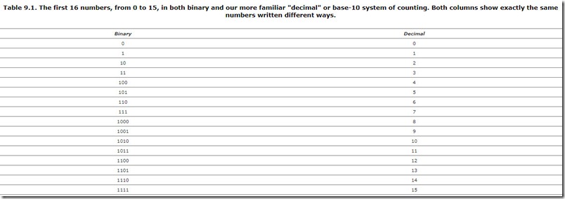
Table 9.1 starts you off with the first 16 numbers written out in both the binary system and our more familiar system with 10 numbers. Binary numbers obviously take more space to write than “normal” numbers because each digit is less powerful, so to speak. It’s really the same number in both columns; they just look different. By the same token, Chinese calligraphy takes less space to write than English words because the Chinese characters are more compact. They say more with each character. Yet both English and Chinese newspapers can say the same things; they just look different.
As funny as it looks, the binary system of numbers is just as useful and just as powerful as our own. There’s no limit to the size of binary numbers; infinity is still infinity, no matter how you write it. Computers use binary numbers to balance our checkbooks, play games, and surf the Web. Unless you’re a computer programmer, you’d never notice your PC was using such a strange system of numbers. If you are a computer programmer, you quickly become accustomed to this alternate number system, like learning to read a second language.
The binary, or digital, system was chosen by the early computer engineers because it is so easy to create using electricity. Simply passing a small voltage down a wire is like sending the number 1. More wires creates more number positions, so five wires can send five-digit numbers from 00000 (zero) to 11111 (thirty-one). Twenty wires can send even bigger numbers, and so on. As we saw in Chapter 6, “Essential Guide to Microprocessors,” a 32-bit microprocessor chip uses 32 wires at a time to store, send, and receive numbers.
Gates and Logic Functions
The binary/digital system explains how numbers work, but how do chips do things? When you turn the power on, how does a communications chip communicate? Why does a graphics chip make graphics? How does a microprocessor decide when to beep or how to run a word processor?
Deep down, all these chips are amazingly, stupendously stupid. They are not endowed with any uncanny form of intelligence or magical powers. They are just very carefully and laboriously built up from the most basic building blocks by patient and talented engineers. It’s the intelligence of the engineers, not the chips themselves, that is impressive.
All digital chips, from memories to microprocessors and everything in between, are built up from just four basic functions called logic gates, plus memory. Like four different shapes of Lego blocks, these four basic gates can be combined to create virtually anything. High-end microprocessor chips contain more than a million of these gates, like a million Lego blocks. Although the individual blocks themselves aren’t particularly impressive, the million-block creations certainly can be.
Explaining how to combine a million of these gates is a subject for a four-year engineering degree. Explaining how the individual gates work is the subject of our next section.
Logic, Binary, and Digital Concepts
Gates, as we said, are the simplest kind of digital electronic function. (Analog chips have different functions.) They’re one step up the evolutionary ladder from transistors, like bricks compared to mud. Silicon makes transistors, transistors make gates, and gates make interesting digital chips like microprocessors and memories.
Gates come in four basic types, which we review one by one. Each gate is designed to perform one simple “logic” function. Logic functions are not like math, not like adding or subtracting. Logic functions are more like “if-this-happens-then-that-must-happen” type of situations.
Logic problems deal with concepts of true and false. Chips, of course, have no such civilized philosophical concepts as truth and falsehood; those are just nice words that we use to label the two conditions that logical gates can manage.
Two conditions? If that sounds to you a bit like the earlier discussion of binary and digital concepts, you’re exactly right. The 0 and 1 from binary numbers are the same as true and false conditions of logic gates. It’s all one and the same. Software programmers call it binary, hardware engineers call it digital, and logic specialists call it—are you ready?—Boolean algebra.
Regardless of the terminology, it all boils down to electricity passing through a wire. To a programmer, that small electric current represents the number 1 and the lack of current is the number 0. To an electrical engineer, that same electrical current would be called an asserted signal; no current is a negated signal. To someone using logic gates, that electrical current is the condition “true” and the lack of current is the condition “false.” They’re all just applying different human concepts to the same physical phenomenon as a handy way to grasp and understand what’s happening.
Tradition says that the binary number 1, the digital concept of asserted, and the logical value true are all the same thing. Likewise, 0 is the same as negated, which is the same as false. We’ll use that notation throughout this chapter.
NOT Gate
The simplest gate is the NOT gate, also called an inverter. It has just one input wire and one output wire. The electricity coming into the NOT gate on the input wire determines what will happen on the output wire. The NOT gate follows a very simple rule to make this happen. It couldn’t be easier. If the input wire is true (i.e., if it is carrying an electric charge), then the NOT gate makes its output wire false (shuts off the electric charge). On the other hand, if the input wire is false (no electricity) then the NOT gate makes its output true (electricity).
Table 9.2 shows how this works. In the table, 1s represent true and 0s represent false. The NOT gate merely does the opposite of whatever is happening on its input wire. In a sense, it turns the electric current upside down. In logical terms, it converts true to false and false to true. In digital terms, it converts assertion to negation and vice versa.
NOT gates are very simple for engineers to build from just four or five transistors. NOT gates also work very fast, processing their input and asserting or negating their output in less than a nanosecond. That is, electricity passes though the NOT gate in less than one-billionth of a second, or about the time it takes light to travel 6 inches.
AND Gate
Apart from the NOT gate, most gates have two wires going into them and one wire coming out. This opens up the possibility for the gate to make a simple decision based on its two input wires. The electricity coming into these two input wires determines what will happen on the output wire.
When you have two inputs, there are only four possible combinations those inputs can be in. You can have both inputs false; first one, and then the other input can be true; or both can be true. Once again using the numbers 1 and 0 to represent true and false, those four combinations can be written as 00, 01, 10, and 11. That’s the notation used by electrical engineers and computer programmers, so we use it here as well.
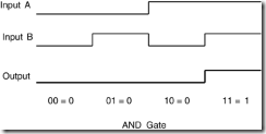
Table 9.3 shows what an AND gate will do under those four conditions. An AND gate is called that because it only asserts its output if the first input and the second input are both true. If either one is false (negated), the AND gate negates its output wire. You could say that an AND gate detects unanimous inputs.
Figure 9.1 shows the same function drawn a different way. Table 9.3 is called a truth table because it treats the four conditions as true or false. Figure 9.1 is called a waveform diagram and it shows the inputs and the outputs as high or low lines that change over time. These diagrams look a bit like heart monitors on a hospital EKG machine. Unlike with those machines, a low, flat line is no cause for concern.
Gates can have more than just two inputs. Table 9.4 shows how an AND gate works if it has three inputs. With three inputs, there are twice as many possible combinations of inputs, and all eight of these conditions are shown in the table. As you can see, the three-input AND gate asserts its output only if all three of its inputs are all true. This is logically the same as the two-input AND gate, but with more inputs. Just as in real life, the more inputs you have, the harder it is to reach a unanimous decision.
OR Gate
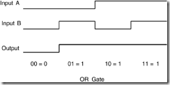
An OR gate asserts its output if one input or the other is asserted. This function is shown in Table 9.5 and in Figure 9.2. You could say that an OR gate detects and collects any true inputs. If even one input to an OR gate is true, its output will also be true. Like pulling on the cord to signal a bus stop, one asserted (or assertive) input is just as good as a dozen.
Gates have no concept of time; they act on what their inputs are doing right now. If an input wire suddenly changes state (e.g., from true to false) the output of the gate changes right afterward. There is an infinitesimally short time delay between when an input changes and when the gate changes its output in response. This is called the propagation delay, and it is usually measured in billionths of a second. As semiconductor manufacturing progresses, this time delay gets even shorter.
Exclusive-OR
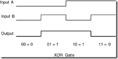
An exclusive-OR (XOR) gate is subtly different from a normal OR gate. If you read down the Output column in Table 9.6, you see that the XOR’s output pattern is 0110, instead of 0111 for the OR gate. The only difference between the two is in the last condition, where both inputs are true. An XOR gate asserts its output when one or the other of its inputs is true, but not when both are true at the same time. You could say an XOR gate detects disagreement. Like a nightclub bouncer preventing two feuding celebrities from entering at the same time, an XOR won’t open its gate if both inputs are present together. An XOR tells you when its inputs are different.
Inverted Gates
Each of the gates we’ve just seen has a twin. They are the inverted, or negated, versions of AND, OR, and XOR gates called NAND, NOR, and XNOR gates, respectively. For instance, the NAND gate works just like a normal AND gate except that its output is reversed. Any time an AND gate would output true, the NAND outputs false, and vice versa. In the physical world, NAND gates are built by simply attaching an inverter (a NOT gate) to the output of a normal AND gate.
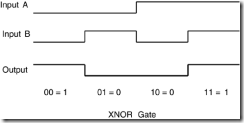
Table 9.7 and Figure 9.4 demonstrate how an inverted XOR gate would work. Reading down the Output column you can see that the XNOR’s outputs are just the opposite of the XOR’s output that was listed in Table 9.6. It’s 1001 instead of 0110. That’s simply because there’s now an inverter stuck onto the output of the XOR to make an XNOR.
An XNOR gate detects agreement. Its output is true only if both of its inputs are identical, either both true or both false.
How Transistors Work
Transistors are the most basic form of semiconductor construction as, as we saw before, the basic mud from which the towering spires of microprocessors, memory chips, and logic gates are built. The path and pace of semiconductor progress are measured by the speed and size of individual transistors, which long ago ceased to be visible to the naked eye. Today’s transistors can be packed more than 10 million to the square inch and operate at nearly the speed of light. There doesn’t seem any way that transistors could become any faster or any smaller, yet they always do.
Transistors have been around since 1947, when the very first one was created in a laboratory in New Jersey. That first transistor was as big as an adult’s fist and very slow by modern standards. The 1960s and 1970s were the dawn of the “transistor age,” as these mighty mites replaced vacuum tubes in radios, televisions, and stereo equipment. Replacing the fragile glass vacuum tubes with tough, solid-state transistors allowed us to put radios in our cars and televisions in our kitchens. Computers could be built to fit in a single room, and cooling them no longer required industrial air conditioning.
Transistors are so plentiful today that they outnumber the human population by more than 300 million to 1. A single transistor is virtually free, in spite of the extraordinarily advanced and expensive technology required to build them.
Transistors work like water valves, opening and closing to permit the flow of electricity at the right time. Yet there are no moving parts in a transistor. They are still and silent, taking advantage of the way electricity passes through certain materials, particularly silicon.
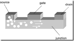
The diagram in Figure 9.5 shows how a transistor is put together. There are three main parts to a transistor, called the source, the drain, and the gate. The source is where electricity flows in, like water. The drain, of course, is where it drains out of the transistor. The gate is like a hand on the spigot, shutting off the flow when appropriate. The junction area shown in Figure 9.5 is simply the material between the other three parts. There are three tiny wires attached to the source, drain, and gate, although they aren’t shown here for clarity.
All three parts of the transistor are made from silicon or materials very much like silicon. The parts are “doped,” or mixed, with other exotic-sounding materials like germanium, selenium, or zinc. The source, drain, and gate are generally all made from the same mixture of materials.
Tech Talk
The source, drain, and gate are sometimes called the collector, base, and emitter, depending on how the transistor is made. The latter terms are more accurate for bipolar transistors, whereas the former describe field-effect transistors (FET) or metal-oxide semiconductor (MOS) transistors, which are used in almost all ICs.
A wire attached to the source supplies electrons and a wire attached to the drain takes them away. To get there, the electrons (the constituent parts of electricity) must pass through the junction area. Usually they have no problem doing this and electricity flows freely, like an open tap. If you apply a small electric voltage to the gate, however, the flow stops. Charging the gate sets up a barrier in the silicon below it, stopping the electron flow halfway through the junction. This barrier is not a physical wall, of course. It’s a more like a magnetic barrier or a science-fiction force field. It’s a gentle barrier, but strong enough to stop electrons from passing underneath the gate as they try to flow from the source to the drain.
The force-field barrier is the key to the whole transistor and the entire semiconductor industry. Silicon is not the only substance that will make a barrier like this, but it’s among the most useful and inexpensive. Metals, plastics, ceramics, and other materials don’t act this way. Silicon is called a semiconductor because sometimes it conducts electricity and sometimes it doesn’t.
As you can see, a transistor works like a valve or a light switch. A small electric voltage applied to the gate can control a large electric current passing through the source and drain. This makes transistors amplifiers in the broadest sense: A small change here makes a big change there. It also makes them ideal components for digital chips. One transistor’s drain can control another transistor’s gate, and so on. Connecting transistors in complex and interrelated patterns is what semiconductor design is all about.
About Electrons and Electronics
Electricity is a lot like water. It flows from one place to another, it can be shut off with appropriate valves, it can be stored for a while, and it can be used to power big mills. A steady flow of electricity is even called a current.
Like water, electricity likes to flow downhill. In electrical terms, that means it flows from wherever there is an excess of electrons to anyplace there is a shortage. Benjamin Franklin labeled these positive (+), for the “uphill” side where electricity is plentiful and negative (–) for the “downhill” side. We’ve used his nomenclature ever since, and you can see it marked on batteries.
Electricity even has water pressure. The amount of electricity flowing from one place to another (from the positive source to the negative drain) is called the voltage. A big, wide garden hose can move a lot of water, and big, thick wires can carry a lot of voltage. Water pressure determines how far the water squirts out of the garden hose, and it can fluctuate at different times of the day. Likewise, electricity can have high or low pressure, called amps. Lots of volts means lots of electrical flow; lots of amps means lots of electrical pressure.
That describes electrical current, but what is electricity, really? Once again, we can compare it to water. The current in a river is made up of an uncountable number of water molecules, and by the same token, electric currents are made of individual electrons. What are electrons?
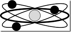
We’ve all seen pictures of an atom like the one in Figure 9.6, which shows electrons circling around a nucleus, like planets around the sun. (It turns out that physicists don’t consider this 1950s-era model to be accurate anymore, but it’s close enough for our purposes.) There happen to be three electrons in our example, but if you remember your high-school chemistry, there can be dozens of electrons per atom, depending on what material it is. Silicon has 14 electrons in every atom, for example.
It so happens that electrons can be stripped off an atom and given to another atom. This creates an imbalance that the electrons themselves try to fix, as shown in Figure 9.7. They are attracted back to their “home” atom like magnets to a refrigerator door. If we strip a few electrons off of Atom A and give them to Atom B, then Atom B will have a surplus and Atom A will have a shortage. If the atoms are close together, the excess electrons migrate back to Atom A all by themselves. If we space the atoms too far apart, however, our emigrant electrons won’t be able to make the trek and the two atoms will be permanently imbalanced. They will keep trying, however.
If we place some other atoms between Atom A and Atom B, the lonely electrons will eventually find their way back home. They do this in a kind of “bucket brigade” fashion. Atom A (which is missing two electrons) will steal two electrons from its nearest neighbor atom. That atom will, in turn, make up its own shortage by stealing two electrons from its neighbor, on so on. Eventually, this chain of compulsive theft ends at Atom B, which had two extra electrons anyway, and all our atoms are once again in balance.
Sometimes this works better than others. It depends on what kinds of atoms are between Atom A and Atom B. Many types of atoms won’t give up their own electrons easily, so they put a stop to this migration. Other types of atoms are more than happy to cooperate. We call the first class of materials insulators. Plastic, rubber, porcelain, wood, and many other materials are insulators, which is why the electrical outlets in your home have plastic safety covers to prevent the electricity from migrating into your hands. Materials in the second category are called conductors. Metal makes a good conductor, which is why all your house wiring and electrical plugs are made of metal. A few materials fall somewhere in between, and we call these semiconductors.
Tech Talk
In a sense, the electrons don’t really migrate from Atom B back to Atom A. It’s really the shortage of electrons that moves from A over to B. Benjamin Franklin was wrong; it’s the electron holes that move from the positive side to the negative side, not the other way around.
Electronics is all about controlling the flow of electrons and electron holes from where they are to where they want to be. We use metal wires when we want the electricity to flow fast and easily, and rubber or plastic insulators to keep it from places we don’t want it to go. We construct elaborate chips out of semiconductors when we want to control when, how, and where the electrons should migrate. That, dear reader, is how semiconductors work.
