Retardation or Running Down Test
This method is applicable to shunt motors and generators and is used for finding stray losses. Then, knowing the armature and shunt Cu losses at a given load current, efficiency can be calculated.
The machine under test is speeded up slightly beyond its normal speed and then supply is cut off from the armature while keeping the field excited. Consequently, the armature slows down and its kinetic energy is used to meet the rotational losses i.e. friction, windage and iron losses.*
As shown in Fig. 31.12, a voltmeter V is connected across the armature. This voltmeter is used as a speed indicator by suitably graduating it, because E µ N. When supply is cut off, the armature speed and hence voltmeter reading falls. By noting different amounts of voltage fall in different amounts of time, a curve is drawn be- tween time and the speed (obtained from voltage values) as shown in Fig. 31.13.
From any point P which corresponds to normal speed, a tangent AB is drawn.
(ii) Finding Moment of Inertia (I)
(a) First Method–where I is calculated.
First, slowing down curve is drawn with armature alone. Next, a fly-wheel of known moment of inertia I1 is keyed onto the shaft and slowing down curve is drawn again. Obviously, slowing down time will be longer due to combined increased moment of inertia of the two. For any given speed, (dN/dt1) and (dN/dt2) are determined as before. It should be noted that the losses in both cases would be almost the same, because addition of a fly-wheel will not make much difference to the losses.
Hence, from equation (ii) above
Second Method–where I is eliminated.
In this method, first, time taken to slow down, say by 5%, is noted with armature alone. Next, a retarding torque–mechanical or preferably electrical, is applied to the armature and again time is noted. The method using electrical torque is shown in Fig. 31.12. The double-throw switch S while cutting off the armature from supply, automatically joins it to a non-inductive resistance R as shown. The power drawn by this resistance acts as a retarding torque on the armature, thereby making it slow down comparatively quickly. The additional loss is I 2 (R + R) or VI , where Ia = average current through R ; V = average voltage across R.
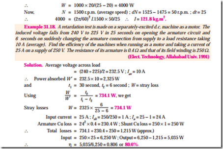
Example 31.16. In a retardation test on a separately-excited motor, the induced e.m.f. in the armature falls from 220 V to 190 V in 30 seconds on disconnecting the armature from the supply. The same fall takes place in 20 seconds if, immediately after disconnection, armature is connected to a resistance which takes 10 A (average) during this fall. Find stray losses of the motor.
(Adv. Elect. Machines, A.M.I.E. Sec. B, 1992)
Example 31.19. A retardation test is carried out on a 1000 r.p.m. d.c. machine. The time taken for the speed to fall from 1030 r.p.m. to 970 r.p.m. is :
(a) 36 seconds with no excitation
(b) 15 seconds with full excitation and
(c) 9 seconds with full excitation and the armature supplying an extra load of 10 A at 219 V. Calculate (i) the moment of inertia of the armature in kg. m2 (ii) iron losses and (iii) the mechanical losses at the mean speed of 1000 r.p.m.
Solution. It should be noted that
(i) when armature slows down with no excitation, its kinetic energy is used to overcome mechanical losses only ; because due to the absence of flux, there is no iron loss.
(ii) with excitation, kinetic energy is used to supply mechanical and iron losses collectively known as stray losses.
(iii) If I is taken in kg-m2 unit, then rate of loss of energy is in watts.


