Merits of Hopkinson’s Test
1. Power required for the test is small as compared to the full-load powers of the two machines.
2. As machines are being tested under full-load conditions, the temperature rise and the commutation qualities of the machines can be observed.
3. Because of full-load conditions, any change in iron loss due to flux distortion at full-load, is being taken into account.
The only disadvantage is with regard to the availability of two identical machines.
Example 31.10 (a). In a Hopkinson’s test on two 220-V, 100-kW generators, the circulating current is equal to the full-load current and, in addition, 90 A are taken from the supply. Obtain the efficiency of each machine.
Solution. Output current of the generator
Solution. In Hopkinson’s test (on two identical d.c. shunt machines), since the two machines are coupled, the speed is common and is decided by the field current of the motor. The field windings of both the machines are in parallel with a separate D.C. source.
Since the machines are identical and are running at the same speed, their e.m.fs are in proportion to their field currents.
Since EA is larger than EB, Machine A supplies power to Machine B. It means, A is working as a generator, and B is motoring.
Example 31.11. Two shunt machines loaded for the Hopkinson’s test take 15 A at 200 V from the supply. The motor current is 100 A and the shunt currents are 3 A and 2.5 A. If the armature resistance of each machine is 0.05 ohm, calculate the efficiency of each machine for this particular load-condition. (Bharathithasan Univ. April 1997)
Solution. Line current into armature circuits = 15 A, Motor armature copper-loss = 500 W Motor-armature-current = 100 A, Generator armature copper loss = 361 W
Hence generator-armature-current = 85 A
For each machine, No load Mechanical losses + Core-loss + Stray losses
Special Note: 15 A current for d.c. supply is related here to armature-input for two machines which are under back-to-back regenerative tests. There are different variations in handling and giving the test data. It is always desirable to draw the circuit diagram according to which the calculations are being related.
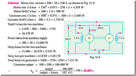
Example 31.13. In a Hopkinson’s test on a pair of 500-V, 100-kW shunt generators, the follow- ing data was obtained :
Auxiliary supply, 30 A at 500 V : Generator output current, 200 A Field currents, 3.5 A and 1.8 A Armature circuit resistances, 0.075 W each machine. Voltage drop at brushes, 2 V (each machine).
Calculate the efficiency of the machine acting as a generator.
(Elect. Technology-1, Gwalior Univ. 1986)
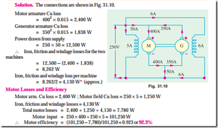
Example 31.14. Explain the Hopkinson’s test on a pair of shunt motors.
In such a test on 250-V machines, the line current was 50 A and the motor current 400 A not including the field currents of 6 A and 5 A. The armature resistance of each machine was 0.015 W. Calculate the efficiency of each machine. (Adv. Elect. Machines, A.M.I.E. Sec. B, 1991)
Related posts:
Incoming search terms:
- Hopkinsons test
- hopkinson test on a pair of dc shunt machine
- hopkinson test problems
- hopkinson test circuit diagram
- hopk8nson tes
- how to find efficiency in two identical machins
- Hopkinsons test on dc shunt machine theory
- problems on hopkinsons test
- hopkinsons example calculatiins
- hopkinson test dc shunt machine theory
- explain Hopkinsons test?
- hopkinsons test theory
- Hopkinson test solved example
- hopkinsons test on dc shunt motor
- numericals on Hopkinson test
- Hopkinson test with sketch
- hopkinson with auxiliary
- merit of hopkinsons teat
- john philemon hopkinson generator diagram
- in hopkinson\s test for dc motors
- In a Hopkinsons test on a pair of 500V 100KW shunt generator
- hopkinsons test solved example
- hw to find iron losses in hopkinsons test
- hopkinsons test conclusion
- hopkinsons test on dc machines theory
- hopkinsons test on dc shunt machines theory
- hopkinson\s test on a dc shunt machines theory
- hopkinson\s test dc shunt machine theory
- hopkinsons test calculation
- hopkinson test uses
- hopkinson test on electrical machines
- describe hopkinsons test in video
- derivation on hopkinsons test
- dc machine determine by using hopkinsons test
- conclusion for hopkinsons test
- conckusion gor test on hopkinson test
- commutation condition under hopkinson test
- Circulating currrent in hopkinson
- Applications of hopkinson test
- examples for Hopkinsoms test
- hokinson test problem find efficiency
- hokinsons test on 2 shunt machines detemine the efficiency of the machine working as agenerator
- hopkinson on a d c machine
- hopkinson test calculations
- hopkinson test based numerical with solution
- hopkinson teat#spf=1
- Hopkinson dc calculation examples
- Hopkins test on pair of dc shunt machines
- hopkins test called regenerative test give its merits and demetits
- Hopkins on test


