Pyroelectric detectors
Pyroelectric films are dielectric materials whose surfaces charge when radiated by infrared (IR). Plastics films have been used for this purpose, but the material that is favoured for modern passive infrared (PIR) detection systems is lithium tantalate. The construction of a detector is as a capacitor with one metal plate and the other a pyroelectric material with a conducting surface. Because of the effect of infrared in separating charges on the pyroelectric material (confusingly, but correctly, also called poLariza- tion) the charge and hence the voltage across the plates of a pyroelectric capacitor will alter as the amount of incident infrared radiation is altered.
The time constant is large, so that the response rate to alterations in IR is in the range 0.2-1 Hz. Because the detector is a capacitor, however, there is no DC response, so that a non-moving infrared emitter will not be sensed. In addition, the capacitor has a very high impedance, so that a practical pyroelectric detector consists of the capacitor and a MOSFET constructed as one unit with external connections to the source and drain of the MOSFET. The main applications for pyroelectric detectors are burglar alarms, automatic light-switching and door-opening equipment, and positioning systems.
The main parameters of a pyroelectric detector are noise-equivalent power (NEP), responsivity and frequency response. The NEP for a given source energy, signal rate of change and bandwidth express the lower limit for which the detector is useful, since signals below this limit will be below the noise level. For a typical detector for a source at a colour temperature of 500K, at a frequency of 10 Hz and 1 Hz bandwidth, the NEP figure of 10-9 W is quoted for a lithium tantalate pyroelectric material.
Responsivity can be quoted in terms of either voltage or current output as volts per unit radiant energy or current per unit radiant energy, at a given predominant wavelength or colour temperature of source. A typical figure of voltage responsivity is 3200 VjW. The frequency response of responsivity means the change of responsivity for different modulation frequencies (not radiated frequency), and this, as noted above, corresponds to a low-pass filter action with a peak at less than 1 Hz.
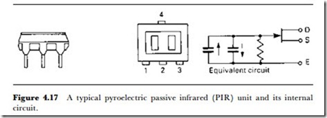
Figure 4.17 illustrates a typical PIR unit, using a DIL IC layout with four pins in a casing approximately 8 x 7.5 mm. The equivalent circuit is of two pyroelectric capacitors connected so that their voltages will add, and with the summed voltages applied to the gate of a MOSFET whose source and
drain terminals are two of the pins of the package. A supply voltage in the range 3-15 V can be used, and the MOSFET is usually wired into a source-follower circuit with a resistor of 100-200 k0. The current consump- tion is 200 JA maximum. The relative response is a maximum for a frequency of 0.2 Hz, falling to 50% at 0.055 Hz and 0.7 Hz, making the unit well suited to respond to movement of humans and animals.
A unit of this type is used in conjunction with a faceted (Fresnel) lens which will focus infrared from an object on to the pyroelectric surfaces and also cause any movement of the object to sweep infrared beams across the detector. The addition of this lens is an essential part of the action, and its construction will also determine the angle over which detection of a moving warm object is effective.
Figure 4.18 shows a typical circuit, using a source-follower connection to the internal MOSFET with a 200 k0 load. The output from the detector is amplified in two stages of a quad operational amplifier, with a voltage gain, overall, of around 3200 – the gain is controllable by the variable resistor in the feedback circuit of IC2. The output from IC2 is passed to a threshold circuit, using a 220 k0 variable resistor to set the threshold voltage at which signals will be passed to the output transistor Tr1, which will amplify and shape the output from the detector. The output is shown operating an LED display with an output to an alarm circuit. In use, the alarm will be turned off when not needed, but the LED is usually kept in operation to indicate that the unit is working correctly.
