The Polarized Field Frequency Relay
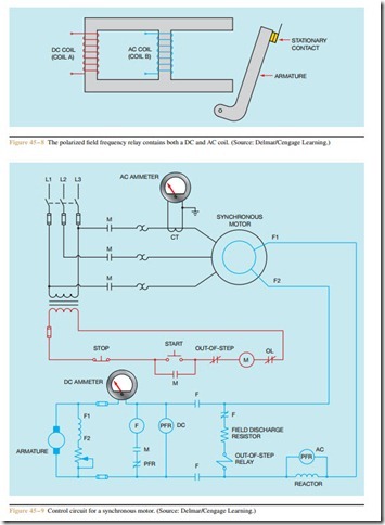
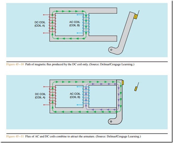
The polarized field frequency relay (Figure 45 – 7) is responsible for sensing the speed of the rotor and con- trolling the operation of the field contactor. The polarized field frequency relay (PFR) is used in conjunction with a reactor. The reactor is connected in the rotor circuit of the synchronous motor. The polarized field frequency relay contains two separate coils, one DC and one AC (Figure 45 – 8). Coil A is the DC coil and is connected to the source of direct current excitation. Its function is to polarize the magnetic core material of the relay. Coil B is the AC coil. This coil is connected in parallel with the reactor (Figure 45 – 9). To understand the operation of the circuit, first consider the path of magnetic flux taken if only the DC coil of the PFR is energized (Figure 45 – 10). Note that the flux path is through the cross bar, not the ends, of the relay. Since the flux does not reach the ends of the pole piece, the armature is not attracted and the contact remains closed.
When the synchronous motor is started, however, the rotating magnetic field of the stator induces an AC voltage into the rotor winding. A current path exists through the reactor, field discharge resistor, and coil of the out-of-step relay. Since the induced voltage is 60 hertz at the instant of starting, the inductive reactance of the reactor causes a major part of the rotor cur- rent to flow through the AC coil of the polarized field frequency relay. Since alternating current is flowing through the AC coil of the PFR, each half cycle the flux produced in the AC coil opposes the flux produced by the DC coil. This causes the DC flux to be diverted to the ends of the pole pieces where it is combined with the AC flux, resulting in a strong enough flux to attract the armature, opening the normally closed contact (Figure 45 – 11).
In this type of control, a direct current generator is used to supply the excitation current for the rotor. When power is first applied to the stator winding, the rotor is not turning and the DC generator is not producing an output voltage. The rotating magnetic field, however, induces a high voltage into the rotor windings, supplying a large amount of current for the AC coil of the polarized field frequency relay. As the rotor begins to turn, the DC generator begins to produce a voltage, supplying power for the DC coil of the PFR. The combined flux of the two coils will cause the normally closed PFR contact to open before the field relay can energize. As the rotor speed increases, less AC voltage is induced in the rotor circuit, and the frequency decreases in proportion to rotor speed. As the frequency decreases, the inductive reactance of the reactor becomes less, causing more current to flow through the reactor and less to the AC coil. The AC coil of the PFR produces less and less flux as rotor speed increases. When the rotor reaches about 90% of the synchronous speed, the AC flux can no longer maintain the current path through the PFR armature, and the DC flux returns to the path, as shown in Figure 45 – 10. When the armature drops away, it re- closes the PFR contact and connects the coil of the field relay to the line. When the field relay energizes, direct current is connected to the rotor circuit and the field discharge resistor and out-of-step relay are disconnected from the line.

