Synchronous Machine Rotor Windings
the presence of faults in rotor winding insulation can sometimes be indicated by a change in machine performance rather than by the operation of a protective relay. For example, if a coil develops a short circuit, a thermal bend may develop due to an asymmetric heat input into the rotor. This could lead to an increase in shaft vibration with increasing excitation current. This change can be used in some cases to determine if the interturn fault is significant. The location and severity of a fault cannot always be found easily even when the rotor is removed. This is especially true in large turbine-generator rotors whose concentric field windings are embedded in slots in the rotor body and covered by retaining rings at the ends. Many ground and interturn failures disappear at reduced speed or at a standstill. This makes their detection very difficult and emphasizes the need for on-line detection technique. The following tests are used to determine if faults exist in the rotor winding and/or indicate their location. Solid-state devices used in exciters should be shorted out before conducting any test involving the induction or application of external voltages to the rotor winding.
Open-Circuit Test for Shorted Turns. An open-circuit test can be used to confirm if shorted turns in rotor field winding exist when there are indirect symptoms such as a change in vibration levels with excitation. The machine should be taken out of service for a short while but does not need to be disassembled.
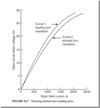
Figure 16.7 illustrates the open-circuit characteristic of a synchronous machine. It relates the terminal voltage to field current while the machine is running at synchronous speed with its terminals disconnected from the grid. The open-circuit curve can be used to verify shorted turns if an open-circuit test characteristic with healthy turn insulation was done previously. A higher field current will be required to generate the same open- circuit voltage if there are shorted turns in a rotor field winding. If the difference between the two curves in more than 2 percent, the possibility of a turn insulation fault will be confirmed. The difference in characteristics to indicate a shorted turn depends on the number of turns in the field winding and the number of shorted turns. For example, a sin- gle shorted turn cannot be detected by this test if the connected field winding has a large number of turns. This test is done while the machine is running at synchronous speed with its stator winding terminal open-circuited and the field winding energized. Generators can easily be driven at synchronous speed because their drivers are designed to operate at synchronous speed. Motors may need to be driven by ac or dc drive at synchronous speed.
If the test indicates the possibility of shorted turns, further confirmation should be obtained by performing additional tests. This test has these limitations:
● It may not detect shorted turns if the machine has a large number of turns and/or there are parallel circuits in the field winding.
● Differences in the open-circuit curve will also be created when the machine’s magnetic characteristics change, for example, when the rotor wedges are replaced with a different material.
Air Gap Search Coil for Detecting Shorted Turns. Interturn faults in rotors are detected by air gap search coils. Methods have been developed for on-line and off-line testing. This technique is especially useful for detecting faults present at operating speed which disappear on shutdown. The coils and slots having shorted turns as well as the number of turns shorted can be identified by this method. Permanent flux probes have already been installed on some machines. Each rotor slot has local fields around it. This leakage flux is related to the current in the rotor. The magnetic field associated with a coil will be affected if the coil is shorted. The search coil records the high-frequency waveform (known as slot ripple) generated in the air gap. Each rotor slot generates a peak of the waveform in proportion to the leakage flux around it. If an interturn fault occurs, the peaks associated with the two slots containing the faulted coil will be reduced. The recorded data are analyzed to identify the faulted coil and the number of (faults). Shorted turns also generate significant levels of even harmonics (multiples of the frequency) while a fault-free rotor generates only odd harmonics.
The search coil is normally mounted on a stator wedge. A gas-tight gland is required for the leads of the probe. Shorted rotor turns should not be a cause of grave concern if the rotor vibration is not excessive and the required excitation is maintained. A generator can operate adequately for a period of time under this condition. However, these shorted turns are normally caused by serious local degradation of the interturn insulation and possibly major distortion of the conductors. In some cases where static exciters are used, arcing damage and local welding have been found.
It is difficult to interpret the on-load test results from the search coil due to the effects of saturations and magnetic anomalies in the rotor body. More complex and time-consuming detection techniques are required. However, modern on-line monitors have overcome these difficulties. They are designed for use with turbine generators equipped with air gap search coil. The output from the search coil is continuously being processed. An alarm is initiated when a current-carrying shorted turn occurs in the rotor winding.
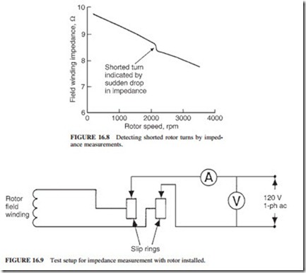
Impedance Test with Rotor Installed. Shorted turns in a field winding can also be detected by periodic measurement of rotor impedance using an ac power supply. These tests should ideally be performed while the machine is operating at synchronous speed because shorted turns may only exist when centrifugal forces are acting on the turn conductors. When the machine is shut down, there may not be any contact, or the fault resistance may be high. Shorted turns can be detected more accurately by impedance rather than resistance measurements. This is due to the induced backward current in a single shorted turn, which opposes the magnetomotive force (mmf) of the entire coil, resulting in a significant reduction in reactance. This technique is particularly effective in salient-pole rotors, where one short-circuited turn eliminates the reactance of the complete pole. There is a sudden change in impedance when a turn is shorted during run-up or rundown (Fig. 16.8). A sudden change of more than 5 percent is needed to verify shorted turns.
The highest field current used for this test should be significantly lower than the normal current required for rated stator voltage at open circuit. The voltage applied should not exceed the rated no-load stator voltage. A normal winding will exhibit a reduction in
impedance up to 10 percent between standstill and operating conditions due to the effects of eddy currents on the rotor.
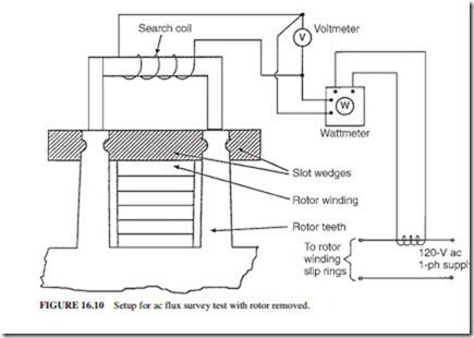
This test can only be performed if the field winding is accessible through collector rings because the low-voltage ac power should be applied while the machine is running. A 120-V, 1-phase, 60-Hz ac power is applied. The voltage, current, and shaft speed are measured. The power supply should be ungrounded because the rotor could get damaged if the field winding has a ground fault.
The test includes these steps:
1. Perform an insulation resistance test on the field winding of the machine to be tested to check for ground faults. The impedance test should not be performed if a ground fault is found. The ground fault should be located using a different procedure.
2. Connect an instrumented and ungrounded power supply to the field winding (Fig. 16.9).
The instruments used should be properly calibrated.
3. Take the reading from the local speed indicator to determine the relationship between impedance and speed.
4. Adjust the field winding voltage to give a maximum permissible current of 75 percent of the current required to achieve the rated open-circuit stator voltage.
GENERATOR SURVEILLANCE AND TESTING 16.15
5. Increase and decrease the speed of the machine while the stator windings are disconnected from the power supply. Measure the current, voltage, and speed starting at zero and increasing the speed at 100 rpm intervals until the rated speed is reached. Continuous measurements can also be recorded simultaneously on a multichannel strip chart recorder.
The values of the impedance (Z = V/I ) should be plotted against the speed (Fig. 16.8). A sudden change in impedance of 5 percent or more or a gradual change of more than 10 percent will indicate a strong possibility of shorted turns in the winding. This test is not as sensitive as the previous two described earlier. It is also important to note that solidly shorted turns will not produce an abrupt change in impedance.
Detecting the Location of Shorted Turns with Rotor Removed. The exact location of a shorted turn should be found to minimize the disturbance to the winding when making repairs. One or a combination of the following procedures should be used:
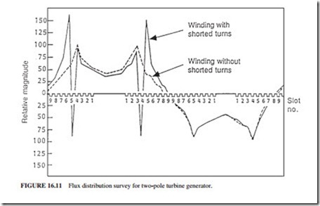
Low-Voltage AC Test. When the field winding of a synchronous machine rotor having shorted turns is connected to a low ac voltage (typically 120 V), the tips of the teeth on either side of the slot(s) having the shorted turns will have significantly different flux induced in them. Figure 16.10 illustrates how the relative magnitudes of tooth fluxes can be measured. The teeth are bridged by a flux survey using a laminated-steel or air-core search coil, which is connected to a voltmeter and wattmeter. The voltage is measured by the voltmeter while the direction of the induced flux is given by the wattmeter. The search coil is moved across all the teeth of the rotor, and voltage and wattage readings are taken. The search coil readings depend on its axial location along the rotor. Therefore, all the read- ings should be taken with the coil located the same axial distance from the end of the rotor. Since the readings vary significantly near the end of the rotor, the coil should not be placed near the end of the rotor. It is important to note that core saturation may occur when a 60-Hz power supply is used. A higher frequency should be used, if possible, to reduce this problem.
The equipment used for the EL-CID test, described later, can be used to detect the shorted field winding turns. This test can be done without removing the end-winding retain- ing rings if the rotor has steel wedges and no damper winding. If the rotor has a separate damper winding or aluminum alloy slot wedges (shorted at the ends) used as a damper winding, they must be open-circuited at the ends before the test can be done. In this case, the retaining rings should be removed. Since many shorts are created by the action of centrifugal forces, they may not appear at standstill.
Figure 16.11 illustrates the flux distribution for a rotor with and without shorted turns. The sharp change in direction of the induced flux indicates the slot containing the shorted turns.
Low-Voltage DC Test (Voltage Drop Test). This method is used to locate the shorts based on dc voltage drop between turns. The end rings should be removed to provide access to the turns. In some cases, the shorts should be induced by applying a radial force to the coils. This is normally done by tapping the wedges with a wooden block or clamping the coils at the corner.
The test is done by applying a dc voltage to the field winding and measuring the drop in voltage across the turns. If a short occurs, the voltage drop across the turn will be lower than normal.
Field Winding Ground Fault Detectors. A large generator rotor operates at 500 V dc and 4000 A normally. If the insulation between the winding and the body is damaged or bridged by conducting materials, there will be a shift of the dc potential of the winding and exciter. The part of the winding where the fault occurred becomes the new zero potential point. In most cases, this will not cause an immediate problem if there is no additional ground fault. A second ground fault in the rotor will be catastrophic.
A rotor ground fault detector is used to enunciate when a fault occurs. Some units are tripped automatically due to possible extensive damage to the rotor body by a dc arc across a separate copper connection. Ground fault detectors have various configurations. The rotor winding is grounded in simple dc schemes on one end through a high ohmic resistance.
However, these schemes become insensitive if the fault occurs close to this end. Ohm’s law determines the magnitude of leakage current from the rotor winding to the ground fault relay. The shaft should also be grounded.
A sophisticated technique was developed to continue operation of a generator having a known ground fault (second ground fault detector). It uses a microprocessor and measur- ing resistors to determine whether the power dissipated by the leakage current exceeds a value that would cause a failure if there were two or more ground faults from the winding. A search coil mounted in the air gap has been used to detect interturn faults and a second ground fault.
If a fault is identified, measurements of slip ring to shaft voltages will give an indication of the location of the fault. (Is the fault at the middle or end of the winding?) After dis- connecting the ground fault detector and while the generator is still on-line, the voltage readings between the brush holders and the shaft are taken. If one ground fault is present, the approximate location of the fault in percent of winding resistance is
During rundown of the unit (when it is unloaded and tripped), an insulation resistance tester is used to test the fault resistance. The brushes are raised or the field circuit breaker is opened to determine if the fault is in the generator rotor, external bus, or exciter. The fault is also monitored as the speed drops. If the fault disappears, it will be impossible to find its location. The operator may decide to put the machine back in service. If the fault reappears when the unit is returned to service, the process should be repeated. If the fault is sustained, a low voltage is applied across the slip rings while the rotor is at standstill. It is usually pro- vided from a 12-V car battery or from a 120-V ac variac. The voltage between the rotor body and each slip ring is measured. If the readings are full voltage with one and zero with the other, there is likely a low-resistance path at the slip rings. It could be caused by carbon dust or insulation failure. It may easily be corrected with a good cleanup. The rotor should be withdrawn if the fault is within the winding. When the rotor is removed, the low-volt- age source is reapplied to the slip rings, and a voltmeter is installed between the rotor body and a long insulated wire. The insulation is removed from the last 5 mm of the wire, and a probe is used to contact the rotor winding metal through ventilation holes and under the retaining rings. This technique will identify the slot, bar, or ventilation hole having the clos- est voltage to the rotor body. The fault is usually located under the wedge near this location. The problem is rectified sometimes by cleaning the ventilation ducts. Otherwise, additional dismantling may be required.
If the ground fault is transient and needs to be found, a failure is forced with a moderate high-potential test and the same technique is used. The hipot test should be used as a last option.
Surge Testing for Rotor Shorted Turns and Ground Faults. This off-line method is used to detect rotor winding faults on stationary and rotating shafts. The location of the fault is identified. This method is very effective in finding ground faults and shorted turns. There is electrical symmetry in a healthy rotor winding. The travel time of an identical electric pulse injected at both slip rings through the winding should be identical. The reflection of the pulse back to the slip rings would also be identical. If there is a short or ground fault, some of the pulse energy will be reflected back to the slip ring due to the drop in imped- ance at the fault. The reflections will change the input pulse waveform depending on the distance to the fault. Therefore, a fault will generate different waveforms at each slip ring unless it is located exactly halfway in the winding.
Recurrent surge oscillography (RSO) is a technique based on the above principle. This test cannot be done on-line because the winding should be isolated from the exciter. Two identical, fast-rising voltage pulses are injected simultaneously at the slip rings. The potential at each injection point is plotted versus time. Identical records should be obtained if there is no fault due to the symmetry in the winding. Differences between the traces are indicative of the winding fault. The fault is located from the time at which irregularity occurred. Ground faults having a resistance less than 500 D will be detected by the RSO method. These faults are also normally detected by the generator protection systems. The RSO technique is used to confirm ground faults. Interturn faults having a resistance of less than 10 D will also be detected by RSO. Faults which have a resistance more than 10 D are more significant during operation and less severe off-load. These faults cannot be detected by RSO.


