AC Tests for Stator Windings
The dc tests are only capable of measuring the conductivity of the insulation system. The ac tests are usually more revealing of the insulation condition. However, they are more onerous than dc tests. The ac tests are also capable of being sensitive to the mechanical condition of the system. For example, if delamination (air-filled layers) is present in the ground wall, the capacitance between the conductors and the core will decrease. However, if the winding is wet, the capacitance will increase.
Partial Discharge Tests. Partial discharges (known in the past as corona) are spark charges which occur in voids within high-voltage insulation (more than 5 kV). They occur between the windings and core, or in the end winding region. These are “partial” discharges because there is some remaining insulation. PD can erode the insulation and therefore con- tributes to its aging. However, PD is a symptom of insulation aging caused by thermal or mechanical stresses. The measurement of PD activity in a stator winding is an indication of the health of the insulation. PD tests provide the best means for assessing the condition of the insulation without a visual inspection. These tests should be done on stator windings in motors and generators rated higher than 5 kV.
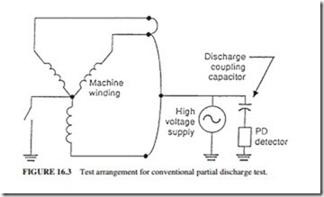
Off-Line Conventional PD Test. The conventional PD test involves energizing the winding to normal line-to-ground ac voltage with an external supply. A PD detector is used to measure the PD activity in the winding. The sparks caused by PD are fast current pulses that travel through the stator windings. These pulses and the accompanying voltage pulses increase with the PD pulse. Figure 16.3 illustrates a high-voltage capacitor that can block the power frequency voltage and allows the high-frequency pulse signals to reach the PD detector. An oscilloscope is used to display the pulse signals, after further filtering.
The pulse magnitudes are calibrated in picocoulombs (pC) even though the actual measurements are in millivolts. The conventional test is done off-line. A separate voltage supply is used to energize the windings to normal voltage. The interference from high-frequency electrical noise in this test is a minimum.
Test Setup and Performance. The conventional test involves isolating the winding from the ground and energizing one phase of the winding by a 60-Hz power supply cable to rated line-to-ground voltage. This test is normally done on each phase separately while the remaining two are grounded. The phases are disconnected from one another at the neutral. Draining of the water-cooled winding is not required.
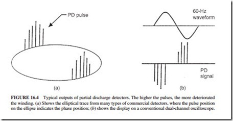
The test equipment includes a power separation filter (high-voltage capacitor and a high-pass filter to block the power frequency and its harmonics, Fig. 16.3). The oscilloscope displays the PD pulses (Fig. 16.4). A pulse height analyzer is used to process the pulse data. It gives the pulse counts, pulse magnitudes, and comparisons between positive and negative pulses.
The ac voltage is raised gradually until PD pulses are observed on the oscilloscope. The voltage at which PD starts is called the discharge inception voltage (DIV). When the test voltage reaches the normal voltage, the magnitude of the pulses is read from the screen. The analysis of the pulse height is normally recorded. As the ac voltage is decreased, the voltage at which the PD pulses disappear is recorded. It is called the discharge extinction volt- age (DEV). It is usually lower than the DIV. The actual test takes about 30 min normally. However, the setup and disassembly can take up to a day.
Interpretation. There is no general agreement on the acceptable magnitudes of PD, DIV, and DEV. The inductive nature of the windings makes the calibration of the measured PD magnitudes (conversion from millivolts on the screen of the oscilloscope into pico- coulombs) difficult. Thus, the measurement of the pulses may not provide an accurate value of the PD activity. These measurements cannot be calibrated from machine to machine or among the different types of commercial detectors.
The most useful method for interpreting the PD test results is by performing the test at regular intervals and monitoring for trends. The recommended interval for air-cooled machines is once or twice per year and 2 years for hydrogen-cooled generators. As the condition of the insulation worsens, the magnitude of the PD will increase and the DIV and DEV will decrease. An increasing trend of PD activity indicates that the insulation is aging. Visual inspection of the winding condition may be required. PD results should be compared only if the same equipment and procedures are used during testing. This is due to the calibration problems mentioned earlier. Comparison of results can also be misleading if there are differences between the types or ratings of the windings. Comparison of PD results are valid if the windings and test methods are identical.
A PD magnitude of less than 1000 pC indicates that the winding should not fail during the next few years. A visual inspection is recommended if the magnitude of PD is more than 10,000 pC, especially if other identical machines have a PD less than 1000 and the insulation is made of epoxy-mica. The DIV in modern epoxy or polyester windings should be greater than one-half the operating line-to-ground voltage. The test indicates that slot discharge is occurring if the DIV value is very low in epoxy-mica windings. However, older asphaltic and micafolium windings may not be in danger even if the magnitude of the discharge is high and the DIVs are low. This is in contrast with newer machines that have synthetic insu- lation, especially Mylar. Their condition deteriorates quickly in the presence of PD. However, older windings should be inspected if there is an increasing trend of PD activity.
There are many disadvantages for off-line conventional PD tests. Since the entire winding, including the neutral end, is fully energized, sites which are not normally analyzed can generate pulses. Large discharges can occur in sites which are not normally subjected to high voltages. This is misleading because the operator may believe that the winding is deteriorating.
On-Line Conventional PD Test. This test is similar to the off-line test except that an external power supply is not used to energize the winding. The generator is driven at normal speed by the turbine, and sufficient field excitation is applied. Therefore, the stator is at the normal operating voltage. The test can be performed with the generator synchronized to the grid or not. When the test is done on a motor, the winding is energized by the normal power supply. Extreme caution is required when the test is performed due to the consider- able risk to personnel and the machine if the capacitor fails.
The test is more realistic than the off-line one because the voltage distribution in the windings is normal. Also, slot discharges that are caused from bar or coil movement are present.
The equipment used in the off-line test can be used in this test. The blocking capacitors are connected to the phase terminals during an outage. Dangerous events can occur if the capacitor fails during the test. An experienced operator can distinguish true PD from electrical interference from brushes, thyristor excitation systems, and background. If the generator is not synchronized, some generators can handle variations in the field current. In these cases, the DIV and DEV can be measured.
Some utilities leave the test equipment connected during normal operation. The PD activity can then be measured at low and full power. Deterioration in the condition of the insulation is detected by an increasing trend of PD. Since the test is done during normal operation, it gives the most accurate indication of the true condition of the insulation. External interference (from power line carrier, radio station, etc.) can be severe during the test, especially in large generators. The interference can be misleading. The operator may believe that high PD activity is occurring while the winding is perfectly good.
Dissipation Factor and Tip-Up Tests. The condition of the insulation system in a high- voltage winding can be evaluated by treating it as a dielectric in a capacitor. The capacitance and dissipation factor (or power factor, or tan o, see note*) of a winding can be measured during an outage. These measurements are normally made over a voltage range. Since partial discharges are initiated when there are voids in the ground wall insulation, the change in dissipation factor with voltage is a measure of the initiation of additional internal losses in a winding.
Machine manufacturers use dissipation factor and tip-up (change in tan o as the voltage is increased or, � tan o) as quality control tests for new stator bars and coils. A general weakness in the bulk insulation, normally caused by incorrect composition or insulation that is not fully cured, is indicated by abnormally high dissipation factor. Excessive voids within the insulation will discharge at high voltage. They are indicated by a higher-than- normal increase in dissipation factor when the voltage is increased (tip-up).
The winding must be isolated into coils or coil groups to obtain a sensitive measurement during this test. This consumes a significant amount of time. Thus, this test is not widely used for testing motors and generators in utilities.
Tip-Up Test. A half-day outage is normally required for a dissipation factor test. It can be performed on motors and generators of all sizes. A single measurement of dissipation factor on a complete winding has limited use. However, trends of measurements on coils or coil groups over years provide useful information. This test is most useful when done on low and high voltage. As the voltage is increased from a low to a high value, the dissipation factor will increase, i.e., tip up. The PD activity within the insulation will increase with the voltage level. Dissipation factor is a measure of electrical losses in the insulation system. It is a property of the insulation. It is desirable to have a low dissipation factor. However, a high dielectric loss does not confirm that the insulation is poor. A capacitance bridge is normally used to measure the dissipation factor. For example, the dissipation factor of a good epoxy-mica and of asphaltic insulation is 0.5 and 3 percent, respectively.
The dissipation factor will not increase with the voltage in a perfect insulation. However, if air-filled voids are present in the insulation, partial discharge will occur at a high enough voltage. The electrical losses in the winding will increase due to energy con- sumption by heat and light generated by the discharges. The dissipation factor will increase with the voltage. As the partial discharge activity increases, the tip-up will increase and the condition of the winding will worsen. Therefore, the PD activity is measured indirectly by a tip-up test. A bridge is used to measure the dissipation factor. It effectively measures the ratio of the in-phase current in the sample to the capacitive (or quadrature) current. This ratio is determined over the total current in the sample. Thus, it represents the average loss over the entire winding being tested.
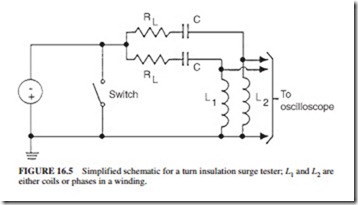
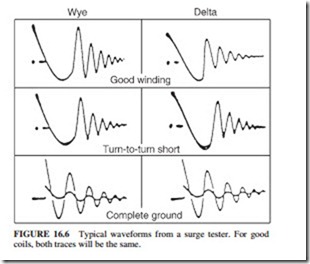
Stator Turn Insulation Surge Test. The surge tests are hipot tests used to check the integrity of the interturn as well as the capability of the ground wall insulation to withstand steep transients that are likely to be encountered in normal service. These surge tests are normally done on new windings in the factory to detect faults. A voltage is applied for a very short time to the turn insulation during the test, causing weak insulation to fail. Thus, the surge test is not a diagnostic test but a hipot test for the turn insulation. The impedances of two matching sections of the winding are compared by commercial surge testers. A volt- age surge having around 0.2-11s rise time and adjustable magnitude is applied simultane- ously to the two winding sections L1 and L2 (Fig. 16.5). The shape of the surges is superposed on an oscilloscope. A high-voltage transient is developed across the winding turns due to the short rise time. The two waveforms will be identical if both windings are free from faults (because the impedances are the same). Any discrepancy in the two wave- forms may indicate a shorted turn in one of the windings. An experienced operator can identify the nature of the fault (Fig. 16.6) by comparing the magnitude and type of the discrepancy between the two waveforms.
In some cases, the surge voltage is applied to an exciter coil, which is placed over the stator coil to be tested (direct connection of the surge tester to a stator coil is not required). This allows testing of coils in complete windings without disconnecting each coil from the other. The voltage is induced into the stator coil by transformer action when the surge is applied. This produces the turn-to-turn stress in the stator coil. However, interpretation of
the result is even more difficult. This “induced” surge test should be carefully done because high voltages may also be induced into coils other than the coil being tested. The test is nor- mally performed by connecting the high-voltage output of the surge tester to two of the phases. The third phase is grounded to the surge tester. The voltage is applied and increased to specified limits, which should not exceed the ground wall dc hipot voltage. If the surge waveforms are identical, the turn insulation is presumed sound.
This test is based on comparing the shapes of surges applied to two winding sections. The two surge shapes may not be identical if the two winding sections being tested have slightly different impedances due to having different dimensions of coils. This will suggest a fault even when the insulation system is in good condition. It is also difficult to detect a turn fault in a coil tested in a circuit parallel with more than 10 coils because a shorted turn will have a minor change in the total impedance of the winding. As the number of coils being tested increases, it becomes more difficult to determine if a defective coil is present. This test does not indicate the relative condition of the turn insulation in different coils. It only indicates if shorts exist. It is a go/no-go proof test like the ac and dc hipot test for the stator ground wall insulation.
Related posts:
Incoming search terms:
- stator winding testing
- testing stator windings
- VERTICAL HV WINDING MACHINES mail
- test for stator winding
- surge comparison test
- stator winding of ac motor
- how to test stator windings
- surge test for high frequency motor
- HV testing of stator winding
- the current in stator windings dc test
- Testing the field windings of an AC motor is very similar to testing the stator windings in a direct current machine True
- testing stator with oscyloscope
- Coils high voltage (HV) mail
- testing of stator bar windings
- test on stator winding
- h V testing of Stator winding
- surge test motor
- high voltage test on stator
- HORIZONTAL HV WINDING MACHINES mail
- motor winding testing instrument
- most ac generator stators use three windings to generate the required amperage output
- AC WINDING SURGE TESTER IN UK


