Stepping motors are devices that convert electrical impulses into mechanical movement. Stepping motors differ from other types of DC or AC motors in that their output shaft moves through a specific angular rotation each time the motor receives a pulse. Each time a pulse is received, the motor shaft moves a precise amount. The stepping motor allows a load to be controlled with regard to speed, distance, or position. These motors are very accurate in their control performance. Generally, less than 5% error per angle of rotation exists, and this error is not cumulative, regardless of the number of rotations. Stepping motors are operated on DC power, but can be used as a two-phase synchronous motor when connected to AC power.
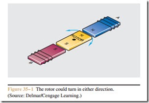
Stepping motors operate on the theory that like mag- netic poles repel and unlike magnetic poles attract. Con- sider the circuit shown in Figure 35 – 1. In this illustration, the rotor is a permanent magnet and the stator wind- ing consists of two electromagnetics. If current flows
through the winding of stator pole A in such a direction that it creates a north magnetic pole, and through B in such a direction that it creates a south magnetic pole, it is impossible to determine the direction of rotation. In this condition, the rotor could turn in either direction.
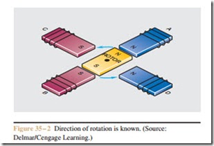
Now consider the circuit shown in Figure 35 – 2. In this circuit, the motor contains four stator poles instead of two. The direction of current flow through stator
pole A is still in such a direction as to produce a north magnetic field; the current flow through pole B produces a south magnetic field. The current flow through stator pole C, however, produces a south magnetic field, and the current flow through pole D produces a north magnetic field. As illustrated, there is no doubt regarding the direction or angle of rotation. In this ex- ample, the rotor shaft will turn 90 degrees in a counter- clockwise direction.
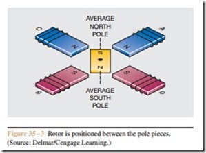
Figure 35 – 3 shows yet another condition. In this example, the current flow through poles A and C is in such a direction as to form a north magnetic pole, and the direction of current flow through poles B and D forms a south magnetic pole. In this illustration, the permanent magnetic rotor has rotated to a position between the actual pole pieces.
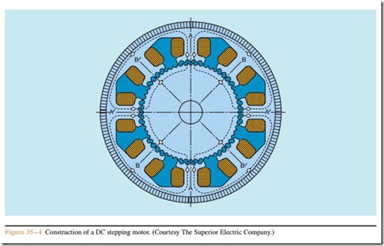
To allow for better stepping resolution, most stepping motors have eight stator poles, and the pole pieces and rotor have teeth machined into them as shown in Figure 35 – 4. In practice, the number of teeth machined in the stator and rotor determines the angular
rotation achieved each time the motor is stepped. The stator-rotor tooth configuration shown in Figure 35 – 4 produces an angular rotation of 1.8 degrees per step.
