Timing
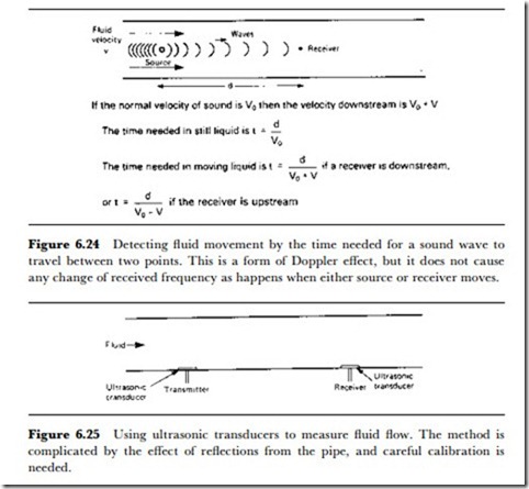
Many sensors of liquid flow are based on the principle that affects waves moving through liquids or gases that may themselves be moving. The equations show how the velocity of a received wave from a stationary source can be affected by movement of the medium that carries the waves, and the relevant equation is illustrated in Figure 6.24. The effect shows that if a wave is detected downstream of the moving liquid that carries the wave, then the time taken to reach the receiver is less than it would be in a liquid at rest. If the wave were moving upstream then the time needed to reach the receiver is greater than it would be in a liquid at rest.
The waves that can be used for measurement can be ultrasonic, and ultra- sonic flow gauges have been commercially available for a considerable time, ever since small ultrasonic transducers became available. Figure 6.25 shows the principle of the method, using in this example the simpler system of a receiver transducer downstream of the transmitter. This makes the velocity of the received wave equal to the natural velocity (in a still liquid) plus the liquid velocity. The change in wavelength is proportional to liquid velocity, and the absolute value of liquid velocity can be calculated with relative ease.
Ultrasonic methods are most useful when they can be applied in large- diameter tubes, using transducers beaming in the line of the liquid flow. Problems arise when the ultrasonic waves are reflected from the sides of the tube or from bubbles or cavities in the liquid, or when the ultrasonic transducers have to be used beaming across the direction of liquid flow. This latter method is, unfortunately, the most practical from the point of view of measuring the liquid flow with nothing immersed in the liquid. For many types of measurement, however, the crossbeam method is completely satisfactory, depending on the liquid and the shape of the cross-section of the tube.
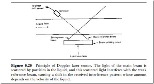
Laser Doppler methods are also in use now, although they depend to some extent on the use of transparent tubes, or tubes with transparent insets, and on the liquid itself being transparent to the laser frequency. One method is illustrated in Figure 6.26, in which the scattering of the light by tiny discontinuities in the liquid (bubbles, for example) is used to cause interference between two parts of a laser beam, causing interference and a frequency shift of the scattered beam. The Doppler laws as applied to light obey the principles of relativity inasmuch as the velocity of the light is constant throughout a medium, irrespective of the movement of the medium. This means that the frequency shifts that are observed are caused by changes of the light wavelength, never by a change of light velocity. A laser fluid-velocity meter based on these principles can operate with liquid velocities of a few mm/s up to several hundred m/s.
Another method that is considerably less simple is the use of correlation techniques. The sensor system consists of a laser beam that is split so that it can be reflected from two different points in the liquid, one downstream of the other. The received signals that are obtained should be identical if one is delayed relative to the other with a delay equal to the time taken for the liquid to traverse the distance between the beams. Figure 6.27 shows the principle as applied to one reflecting particle in the liquid. The use of the technique depends on electronic methods of correlating the readings, and digital circuits consisting of exclusive-OR gates are used. For calibration, bubbles may have to be injected into the liquid, but most liquids will provide sufficient natural discontinuities to make the system workable.

