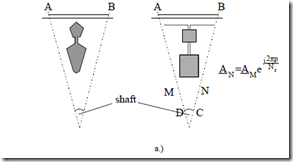
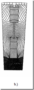
The FEM has so far proved successful in predicting the main path flux saturation or the magnetization curve Lm(Im). It has also been used to calculate the general shape deep bar [17] and double cage bar [19] resistance and leakage inductance for given currents and slip frequency (Figure 9.34).
The essence of the procedure is to take into consideration only a slot sector and apply symmetry rules (Figure 9.34b).
Figure 9.34 a.) Deep bar and double-cage rotor geometry; b.) FEM flux line
The stator is considered slotless and an infinitely thin stator current mmf, placed along AB, produces the main flux while the stator core has infinite permeability. Moreover, when the stator (and rotor) mmf have time harmonics, for inverter-fed situations, they may be included, but the saturation background is “provided” by the fundamental to simplify the computation process. Still the zig-zag and skewing flux contributions to load saturation (in the teeth tips) are not accounted for.
The entire machine, with slotting on both sides of the airgap and the rotor divided into a few axial slices to account for skewing, may be approached by modified 2D-FEM. But the computation process has to be repeated until sufficient convergence in saturation then in stator and rotor resistances and leakage inductances is obtained for given voltage, frequency, and slip. This enterprise requires a great amount of computation time, but it may be produced more quickly as PCs are getting stronger every day.
PERFORMANCE OF INDUCTION MOTORS WITH SKIN EFFECT
As already documented in previous paragraphs and in Chapter 7, the induction machine steady state performance is illustrated by torque, current, efficiency, and power factor versus slip for given voltage and frequency.
These characteristics may be influenced many ways. Among them the influences of magnetic saturation and skin effects are paramount.
It is the locked-rotor (starting) torque, breakdown torque, pull-up torque, starting current, rated slip, rated efficiency, and rated power factor that interest both manufacturers and users.
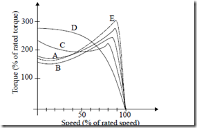
In an effort to put some order into this pursuit, NEMA has defined 5 designs for induction machines with cage rotors. They are distinguishable basically by the torque/speed curve (Figure 9.35).
Design A.
The starting in-rush current is larger than for general use design B motors, However, starting torque, pull-up and breakdown torques are larger than for design B.
While design A is allowed for larger starting current for larger starting torque, it also larger. These characteristics are obtained with a lower leakage inductance, mainly in the rotor and notable skin effect. Mildly deep rotor bars will do it in general.
Design B.
Design B motors are designed for given maximum lock – rotor current and minimum breakdown, locked-rotor and pull-up torques to make sure the typical load torque/speed curve is exceeded for all slips. They are called general purpose induction motors and their rated slip varies in general from 0.5 to 3 (maximum 5)%, depending on power and speed. A normal cage with moderate skin effect is likely to produce design B characteristics.
Design C.
Design C motors exhibit a very large locked-rotor torque (larger than 200%, in general) at the expense of lower breakdown torque and larger rated slip–lower efficiency and power factor–than design A & B. Also lower starting currents are typical (Istart < 550%). Applications with very high break-away torque such as conveyors are typical for Design C.
Rather deep bars (of rather complex shape) or double cages are required on the rotor to produce C designs.
Design D.
Design D induction motors are characterized by a high breakdown slip, and large rated slip at very high starting torque and lower starting current (Istart < 450%).
As they are below the torque/speed curve D (Figure 9.35) it means that the motor will accelerate a given load torque/speed plant the fastest. Also the total energy losses during acceleration will be the lowest (see Chapter 8, the high rotor resistance case).
The heat to be evacuated over the load acceleration process will be less stringent. Solid rotors made of iron without or with axial slits or slots with copper bars are candidates for design D motors. They are designated to applications where frequent accelerations are more important than running at rated load. Punch presses are typical applications for D designs as well as very high speed applications.
Design E.
Design E induction motors are characterized as high efficiency motors and their efficiency is 1 to 4% higher than the B designs for the same power and speed. This superior performance is paid for by larger volume (and initial cost) and higher starting current (up to 30%, in general).
Lower current density, lower skin effect, and lower leakage inductances are typical for design E motors. It has been demonstrated that even a 1% increase in efficiency in a kW range motor has the payback in energy savings, in a rather loaded machine, of less than 3 years. As the machine life is in the range of more than 10 to 15 years, it pays off to invest more in design E (larger in volume) induction motor in many applications.
The increase in the starting current, however, will impose stronger local power grids which will tend to increase slightly the above-mentioned 3 year payback time for E designs.


