Smoke and fire
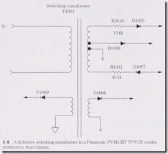
Where there is smoke there is fire, or so the saying goes. This also applies to troubles that occur in the electronic chassis. Suspect a shorted power transformer with smoke and odors rising from the low-voltage circuits. Often, small power transformers with leak”Y silicon diodes or leaky filter capacitors might open the primary winding. In large power or switching transformers, found in high-voltage stereo amplifiers and TV chas sis, the shorted transformer might burn or smoke (Fig. 1-8).
Remove all secondary leads from the power transformer to the power circuits, and let the transformer cool down. Again, turn the chassis on. If the transformer begins to smoke and run excessively wann, replace it. Remember, power transformers are rather expensive and sometimes difficult to obtain.
When liquid is spilled in an area where higher-than-normal voltage is found, firing on the PC board results. Smoke will curl upward and holes will be burned in the board if the unit is left on. Firing and arcing between components and wiring might melt down and destroy a few parts before the chassis is shut off. Arc-over between horizontal and vertical windings in the yoke assembly might be caused by liquid spilled into the yoke or breakdown within the yoke assembly.
Small burned spots on a board can be repaired by replacing burned or charred components. Spray on a cleaner/degreaser to wash away dirt from the parts and circuit board. Scrape off burned areas with a pocketknife or flat tool. Replace burned compo nents with new parts. Recheck for overheating, arcing, and smoke after repairs. Spray on a light coat of premium preservative fluid and let dry.
Often the horizontal output transfonner must be replaced when heavy arcing is found within the high-voltage windings or diodes. Check the flyback for burned areas.
Thm off the chassis and feel the transformer for overheating. A hot area represents shorted internal wiring. Replace the flyback with the original part number. You may be able to see a burned or arcing section of the flyback or no signs at all.
Under those eyes
You can locate many different components within consumer electronics products with your own eyes. Just take a peek at the chassis and notice any burned areas or overheated parts. Most symptoms are found by sight, sound, or touch. Of course, test equipment is needed to check voltage, resistance, current, waveforms, and continu ity of the various components. Isolating and pinpointing the defective part are the most difficult jobs in troubleshooting. It only takes a few minutes to replace a defec tive part after locating it.
Sometimes we try too hard to locate a problem when the defective part is staring up at us, right under our eyes, so to speak. It is best to get away from the chassis when a defective part cannot be found in 1 hour. The longer you stay with it, the more dark and clouded the scene becomes.
A little common sense, electronics knowledge, the correct test equipment, and ex perience can help you locate the “tough dog.” When the mind is free and clear, early in the morning, tackle that tough repair problem. Happy hunting.
Keep at it
After working on a chassis for several hours, you rnight want to give up. Why not try a different approach or method of troubleshooting? Each electronics technician has his or her Own method of troubleshooting an electronic product and docs not want to change. Have ou tried asking fellow technicians if they have had the sarne prob lein? Help can be obtained from electronics distributors and service departrnents.
Why not ask the manufacturer for help? Help is out there; just ask for it. Some rnan ufacturers have service centers around the country where their electronic products can be serviced.
Don’t give up the ship. Keep your nose to the grindstone, so to speak. Sornetirnes you WOnder if this job is all worth it. You bet it is. There is no greater satisfaction than solving “tough dog” problems.
Same chassis, different model
The electronics manufacturers use several chassis that are the same, year in and year out. The cabinet and outside dressing are changed, but the insides are essentially the same. In fact, the same chassis might be found in other brands of TVs.
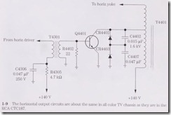
For instance, let’s take the RCA CTC187 TV that has many different chassis, such as the CTC187AJ, CTC187BJ, and CTC187BH. However, you might fmd in a few differ ent manufacturers that the circuits are the same with a different size picture tube. The BJ and BH chassis might have a different sound system than the CTC187AJ chassis. The horizontal and vertical controls and power supplies might be the same in all chas sis. You can service all RCA CTC187 chassis with only one schematic (Fig. 1-9).
Often the horizontal, vertical, and intermediate frequency (IF) circuits are the srune. A different tuner might be used, but the IF sections are identical. The same color lC nlight be used in several dozen TV chassis. So why not try to use a schematic that is similar to the chassis found on your service bench instead of waiting for months for the exact diagrmn?
The same train tracks
Remember, the circuits found on the schematic of a manufacturer might be u’sed in 1nany different chassis. Some firn1s have their own pet circuits that are used in many different chassis, including other brands. In fact, several overseas companies make electronic wlits for other brands. These wuts might not look the sarne, but inside they are the same circuits. For instance, the horizontal circuits are about the same in all models.
When a breakdwon occurs in one chassis, look for the same part to break down in other chassis. Sometimes the same component fails in many different chassis. You can 1nake money on these types of repairs because they occur over and over. However, it is difficult to remember what parts break down in several hundred different chassis each year. write it down.
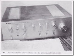
The best place is to write it down is on the service schematic. Circle the defective co1nponent, draw a line out to the side, and write down the symptom. Circle the volt ages that are measured when the part is defective, with proper waveforms (Fig. 1-10). Remember, the same part might break down in another chassis.
Service notes and troubleshooting tips by the manufacturer or service center can be added to the same chassis. If you are a warranty station for several brands of elec tronic products, the firm passes on troubleshooting guidelines that can help in servic ing the “tough dog” chassis. And of course, 1nanufacturers’ service rneetings and seminars are worth their weight in gold. Take a few hours away fron1 the bench to gain valuable knowledge.
Lines down the road
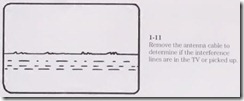
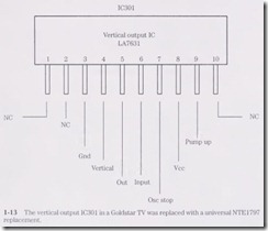
While two yellow lines down the middle of the highvvay divide the conung and going traffic in half, the white lines along the outside edge of the asphalt show the edge of the pavement. Unwanted lines in the TV picture must be erased for good viewing. Sharp, jagged, or dotted lines across the picture can indicate outside interference or arcing in the TV chassis. Outside interference lines can be caused by tnotors, neon signs, and high-power lines arcing over (Fig. 1-11). Remove the antenna wire to determine if the lines are in the set or picked up by the antenna.
A dirty spark gap around the picture-tube socket can cause arc-over. Blow out the dust and dirt within the picture tube socket, or replace the socket. If one of these gaps continually arcs over, it can cause an extremely blurry picture, an out-of-focus picture, loss of color, a raster of one color, or chassis shutdown. Check for arcing under the an ode high-voltage rubber cap assembly. Sometimes it is not hooked properly and comes loose, causing high-voltage arc-over.
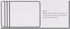
Vertical lines to the left of the picture may result from Barkhausen or improper filtering in the automatic gain control (AGC) circuits (Fig. 1-12). In the early chas sis, Barkhausen lines resulted from a horizontal output tube. Today, heavy-firing ver tical lines can be caused by the horizontal output transistor or flyback transformer. Shunt small electrolytic capacitors in the AGC and sync circuits for vertical lines in the picture.
Identify part numbers
Sometimes you can locate the section with the defective component by looking at the part number stamped on the top. A large vertical output IC, as shown in Fig. 1-13, con tains the vertical input and output circuits. Simply look up the part number stamped on the body area. The part number will tell you not only what circuit it works in but also the correct replacement.
Simply look up the part number in a semiconductor manual for the correct univer sal replacement. You can look at another chassis of the same brand, locate the same IC, and compare the voltage measurements with the other schematic. Not only will the part number indicate what circuit it operates in, but it also will provide the correct working voltage and terminal numbers.
Part numnbers and letters found on ICs and transistors will help you to locate the correct circuit or component and sometimes the operating voltages. RCA, GE, Sylvania, Workman, and NTE semiconductor replacernent manuals cover Alnerican, European, and Japanese solid-state devices. These rnanuals can be obtained frorn rnanufacturers, electronics stores, dealers, and mail-o rder finns.
If the exact hernatic is not available, look on another schernatic frorn the sarne manufacturer using the same part number. Compare the voltage rneasurernents with those of the defective chassis. Sometimes the same part in other brands will have about the same voltage measurements.
Resistor color codes
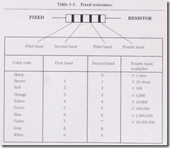
You should be able to learn the color codes of the different resistors and by glancing at a suspected resistor read off the con·ect resistance. After many hours and weeks of servicing electronic chassis, the electronics technician can easily quote the resistance and tolerances by looking at the color stripes on a defective resistor. Sometimes if the part is burned or charred, the color may change and give a different resistance reading. Always replace the suspected resistor with one with the exact resistance and wattage rating (Table 1-1).
Flat capacitor color codes
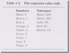
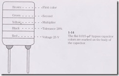
The flat-type bypass capacitor might have only color bands on it with capacity and rated tolerance. This flat-type capacitor has no particular polarity and can be con nected with any type of mounting. The first color at the top is the first number of the capacity. The second color is the next number, and the third color is the multiplier. The fourth color is the tolerance in percentage, and the last color is the working voltage (Table 1-2).
For instance, a 0.015- µF bypass capacitor will have a brown color at the top; next will be the green, yellow, black, and red. The yellovv color is the multiplier, black is the percentage in tolerance, and red is the operating voltage (Fig. 1-14).
Foreign capacitors
Sometimes a foreign electronic product might have the capacity stamped on the chas sis or listed on the schematic. All capacitors should be replaced with the same capacity and voltage or a higher working voltage. Check foreign capacitors against their Ameri can replacements as shown in Table 1-3.
Dogs of all kinds
The “tough dog” problem takes a lot of valuable service time while you scratch your head for the answer. For the headache, you can take an aspirin or Tylenol to relieve the pain. when servicing a “tough dog” problem in the TV, audio, or VCR chassis, nothing relieves the pressure or pain until the component culprit is located. A “tough dog” may end up with more than one trouble or component in the TV chassis.
“Tough dogs” are very difficult to locate without a schematic. In many cases the “tough dog” is right under our nose, so to speak. Isolate the symptom to a given section of the chassis, and take critical voltage and waveform readings. Often the difficult chas sis may have an intermittent component that will only act up once a week or twice a month. These sets should stay in the home until the intermittent state acts up several times a day. Just wait, and they will begin to act up more often.
The intermittent chassis can result from poorly soldered connections, intermittent components, cracked boards, and poor terminal connections. Twist and push around on the board until you have located the intermittent section. Check all component sol dered connections in that area. Sometimes a wholesale resoldering of the entire section may W1cover the intermittent connection.
A large blob of solder may contain a poorly tinned component lead. Often a component lead that is not properly tinned or to which solder will not cling ends up a poor contact. Remove the large blob of solder with solder wick or a sucking tool. Remove the terminal lead. Clean it up, and tin the connections. Rernount and resolder.
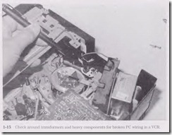
Foil wiring breakage around board standoffs can cause intermittent operation in a VCR. Inspect the PC wiring around where heavy components such as tuners, heat sinks, and transformers are mounted. If the unit is dropped in shiprnent or on delivery, these heavy components can cause cracked PC wiring (Fig. 1-15).
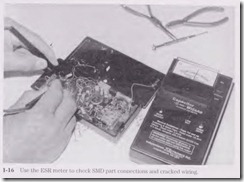
The surface-mounted components found in almost every consumer electronic product can cause an intermittent or dead service symptom. A poorly soldered end con nection can result in a dead or intermittent circuit. A continuity check “With the capaci tor equivalent series resistance (ESR) meter can locate a high resistance or poor end connection of a surface-mounted device (SMD). Like-wise, the ESR meter can locate broken or cracked PC boards (Fig. 1-16).
Another method is to spray coolant directly on the body of the component or parts that require an hour or so of heat-up time. Then apply hot air from an air gun or hair dryer and see if the part returns to the intermittent state. In the end, the “tough dog” symptom can cause high tension, headaches, and an “I do not know anything about electronics” feeling.
