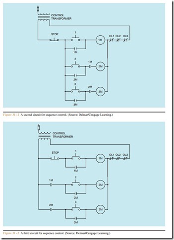
Sequence Control Circuit #3
A third circuit that is almost identical to the previous circuit is shown in Figure 31 – 3. This circuit also employs the use of normally open auxiliary contacts to prevent motor #2 from starting before motor #1, and motor #3 cannot start before motor #2. These normally open auxiliary contacts that control the starting sequence are often called permissive contacts because they permit some action to take place. The main difference between the two circuits is that in the circuit shown in Figure 31 – 2, the stop push button interrupts the power to all the motor starters. The circuit in Figure 31 – 3 depends on the normally open auxiliary contacts reopening to stop motors #2 and #3.
Related posts:
Binary number System:Binary numbers
Power Quality Test Instruments
LEAKAGE SATURATION INFLUENCE ON AIRGAP CONDUCTANCE
D.c. Motor:Motor Principle
ELECTRONIC GADGETS AND HOME APPLIANCES – WASHING MACHINES
Measurement:Combining Decibels
Special machines:Permanent-Magnet DC Motor
PNEUMATIC CONTROL FUNDAMENTALS:PNEUMATIC CENTRALIZATION
Objective tests on alternators.
AUDIO AND VIDEO SYSTEMS - POWER SUPPLIES
Multicore Cables and Cabletray:Cable Tray Installations
CONTROL FUNDAMENTALS:HEATING EQUIPMENT
VIBRATION ANALYSIS:FREQUENCY DOMAIN
PERFORMANCE AND OPERATION OF GENERATORS:OPERATIONAL LIMITATIONS
