 GENERATOR TESTING
Tests should be done on the generator during the outage to monitor its condition and to ensure that it is in a satisfactory state for return to service, following maintenance. A major overhaul of the generator should be done every 8 years. Details about the tests were provided in Chap. 16. The following paragraphs provide practical information about these tests.
Insulation Testing
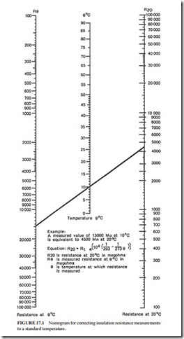
Insulation Resistance (IR) Measurement. The insulation resistance test consists of a measurement of the dc resistance between the winding and ground, or between two windings. It is normally performed using a battery- or mains-powered megohmmeter. The test voltage on rotors is typically 500 V dc (the diodes should be disconnected before performing the test). The test voltage for stators up to 6.6 kV is 1 kV dc. It is 5 kV dc for higher stator voltages. The IR test results should be corrected to a standard temperature of 20°C. Figure
17.1 illustrates a nomogram used for this purpose. The IR results are also affected significantly by humidity if the insulation system is open to the atmosphere. Dry air should be blown through water-cooled windings following draining to remove the water from all the hoses. This is necessary to obtain satisfactory IR readings.
Polarization Index Test. The polarization index (PI) test is an extension of the insulation resistance test. The dc voltage is applied across the insulation for 10 min. The PI is the ratio of the insulation resistance reading obtained after 10 min to the reading obtained after 1 min. The insulation condition is considered acceptable if the PI is greater than 2. Lower values of PI indicate the presence of surface contamination such as dirt or moisture on the insulation. If the PI value is lower than 2 and the 1-min IR reading is low, serious degra- dation of the insulation may have occurred. The extent of the degradation in the insulation can only be determined by the loss angle test.
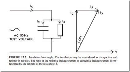
Loss Angle Test. The loss angle (or tan delta) test is used to determine the condition of the insulation. Voids develop in the insulation as it deteriorates, resulting in a change in capacitance of the winding. The loss angle ( ) changes due to the change in capacitance of the winding (Fig 17.2).
The test is performed as follows:
● Confirm that the winding has a satisfactory IR reading.
● Apply ac voltage (60 or 50 Hz) to the winding.
● Increase the voltage from 20 to 100 percent of the line voltage V1 in increments of 0.2V1.
● Record the capacitance and tangent of the insulation loss angle at each step, using an ac bridge.
● Discharge the winding following completion of the test. This step is necessary to ensure the safety of personnel working with this equipment.
17.8 CHAPTER SEVENTEEN
FIGURE 17.1 Nomogram for correcting insulation resistance measurements to a standard temperature.
GENERATOR INSPECTION AND MAINTENANCE 17.9
FIGURE 17.2 Insulation loss angle. The insulation may be considered as a capacitor and resistor in parallel. The ratio of the resistive leakage current to capacitive leakage current is rep- resented by the tangent of the loss angle, .
The tan delta should be plotted against the line voltage. The test results are affected by the following factors:
● Presence of cooling water in the winding
● Type and pressure of gas inside the generator
● Amount of surface contamination on the windings
The condition of the insulation is determined by comparing the test results with other tests performed on the same and similar machines.
High-Voltage Tests. High dc voltage tests that subject the winding to a higher voltage than the normal operating voltage are rarely performed on a commissioned generator. However, proof voltage tests are performed normally following repair. The actual test volt- age depends upon the repair and the condition of the machine. These tests should be per- formed in a CO2, nitrogen, or pure hydrogen environment to remove the risk of fire.
Testing the Stator Core
Following removal of the rotor from the generator, the stator core should be examined for evidence of damage or breakdown in the core plate insulation. The following two methods are used commonly:
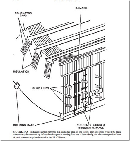
Ring Flux Test. A flux is induced in the core by using several turns of heavy high- voltage (HV) cable wound toroidally around the core and supplied from a voltage source of 3 to 14 kV. The pulsating magnetic flux induced in the core is similar to the rotating flux induced while the machine is operating. Hot spots will appear in the core (Fig. 17.3) due to the induced eddy currents in the regions where the interlaminar insulation (between the core laminations) is damaged. An infrared camera is used to detect these regions. This test is difficult to perform, expensive, and time-consuming.
The Electromagnetic Core Imperfection Detector (EL-CID) Test. One turn of a light conductor is wound in a similar fashion as above around the core to generate a small flux in the core. The conductor is normally supplied from 120 or 240 V ac. The conductor will carry a current in the range of 13 to 30 A (depending on the voltage source). The EL-CID detector contains a pickup coil which detects the magnetic flux induced in the air by the small fault currents flowing in the damaged region. The detector is scanned along the conductor slots inside the stator, and battery-operated electronic circuits are used to identify the faults.
The EL-CID method can identify the majority of faults in the core. It has become the preferred method for core testing due to its simplicity and low cost. Fine grinding or etching techniques are used sometimes to rectify the local areas of core damage.
Stator Coolant Circuit Testing
Following maintenance work on the stator, it is necessary to prove that the windings, hoses, and manifolds within the stator frame are watertight. This can be done by performing a vacuum loss test. It consists of drawing a 700-mbar vacuum in the winding and observing the change in pressure over a 12-h period. The manufacturer would normally specify the maximum permissible change in pressure. A typical 660-MW stator should drop around 10 mbar within 12 h. If the vacuum test results are unsatisfactory, a mixture of air and 20 per- cent (by volume) of a tracer gas should be pressurized in the winding. A leak search should then be performed, using an electronic gas detector.
Helium or refrigerant gases, such as Arcton or Freon, are used normally as tracer gases. If Freon is used, precautions must be taken to ensure that the concentration of the gas in the generator atmosphere is below the long-term occupational exposure limit. This is the limit of concentration of gas in the air that permits safe work for an 8-h period. The limits of refrigerant gases are listed in health and safety manuals.
Another important check should be done following work that involves opening of the stator water coolant circuit. It is the confirmation that the coolant is flowing through all coils. A bubble check is normally performed on hose-type machines (where coolant flows through translucent PTFE hoses in and out of the winding). Dry filtered air is injected into the stator water system after it has been placed in service. The flow should be examined in all the hoses, as indicated by the movement of entrained air bubbles.
An alternative method for checking the flow should be used in designs where the manufacturer does not recommend filling the winding with water unless the frame has been pressurized with gas. It consists of measuring the temperature increase across each conductor as the pump losses warm up the stator coolant. On other stator designs, it may be possible to measure accurately the total flow through each phase and to compare the values with the flow readings obtained during the commissioning phase of the machine.
Hydrogen Loss Test
A pressure drop test should be performed using air, nitrogen, or CO2 to ensure that the frame is gas-tight. Hydrogen is not used in the test, to avoid the safety hazard that would occur in the event of a leak.
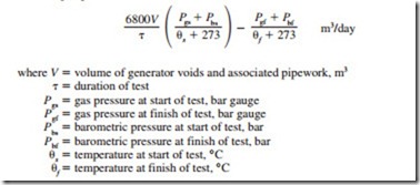
The pressure drop test is performed normally over a 12-h period. The volume of gas lost during the test, at normal temperature and pressure (NTP), can be found using the following expression:
The results of the test should be compared with the manufacturer’s specifications. If the results are not acceptable, the test should be repeated, using a tracer gas such as helium. Gas detectors are used to identify the source of the leak. The leaks should be sealed and the test repeated until satisfactory results are obtained.
Rotor Winding Tests
The installed rotor ground fault detection equipment can be used to detect and measure rotor ground faults on-load. The insulation resistance test is used to identify rotor ground faults during outages. The detection of interturn faults [failure of the insulation between the turns (windings) of the rotor] is more difficult. However, if there is a solid short between the turns, the IR test can identify the interturn fault.
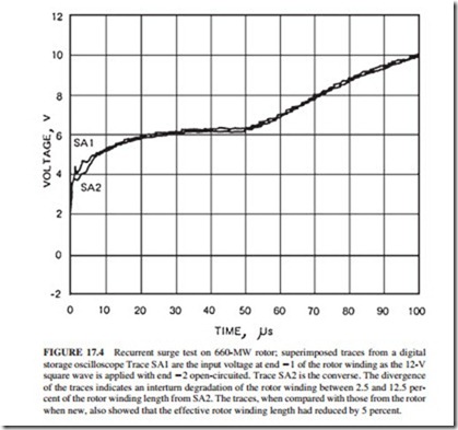
The recurrent surge test is used to identify ground and interturn faults. A 12-V dc square wave is injected through a matching resistor at each end of the rotor winding in turn. The input and output waveforms of both waves are stored and viewed on an oscilloscope. If there is fault in the winding, a reflected wave will travel back to the input, causing a change in the input voltage. The time of this change is proportional to the distance of the fault from the input. The input traces from the two ends of the winding are superimposed to show any divergence between the traces. This will ease the detection of the voltage change described earlier.
The number of shorted turns indicated by the test is proportional to the increase in total transit time of the pulse from the total transit time that was recorded when the rotor was new. This test can be performed while the rotor is rotating on machines having slip rings. This provides the ability to detect the faults that disappear at rest or change with speed. Figure 17.4 shows the traces of a recurrent surge test performed on a 660-MW rotor. It indicates the presence of shorted turns.
Related posts:
Incoming search terms:
- germany Electrical machinery equipment mail
- generator winding damage test
- method of testing generator
- moisture presence in generator
- Core loop testing at 100 percent rated flux
- check carried on a generator
- how to perform a rupture basin test on generator
- ac generator rotor testing
- insulation test result of generator
- polarisation index test for windings scholarly articles
- insulation resistance of test dc generator
- generator winding resistance test procedure
- Winding Equipment mail
- generator diode testing
- generator tests
- generator rotor ground detection temperature
- generator and transformer mail
- tan delta test of generator
- ac generator inspection and maintenance
- how to test generator windings
- generator stator winding test
- generator stator dc resistance test
- generator ir and pi
- generator routine stator testing
- generator rotor transport rack
- winding resistance test of generator
- generator rotor mail
- generator pi test
- generator rotor checking procedure
- generator test times jch
- generator rotor ground detection humidity
- generator stator winding resistance
- check stator on vertex generator
- 660 MW Generator tests
- 660 MW genertor rotor testing
- 660 mw tan delta test procedure
- 660;MW alternator testing and commissioning checklist
- a reminder to test generators
- 660 MW Insulation resistance testing
- aire test generator H2
- Circle-C Transformers - Circle-C transformers producing transformers and associated electrical equipment mail
- conduct alternator insulation resistance test
- core test of alternator
- dc winding resistance test on generator
- Draining machinery and equipment mail
- electical alternator maintenance and testing methods
- electrical generator in hong kong mail
- electromagnetic core imperfection detection
- flux test on alternator 6kv
- gas generation equipment mail
