Audio Mixer Circuitry
Now that we understand the basic architecture of the mixer, it is time to look at each part again and understand the function of the electrical circuits in each stage in detail.
The input strip is illustrated in Figure 27.9. Note that below the VU meter, the topmost control is the channel gain trim. This is usually switchable between two regimes: a high gain configuration for microphones and a lower gain line level configuration. This control is set with reference to its associated VU meter. Below the channel gain are the equalization controls; the operation of these controls is described in detail later.
Microphone Preamplifiers
Despite the voltage amplification provided by a transformer or preamplifier, the signal leaving a microphone is still, at most, only a few millivolts. This is much too low a level to be suitable for combining with the outputs of other microphones inside an audio mixer.
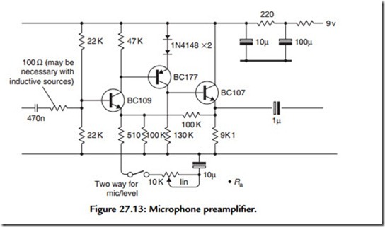
So, the first stage of any audio mixer is a so-called microphone preamplifier, which boosts the signal entering the mixer from the microphone to a suitable operating level. The example given here is taken from a design (Brice, 1990), which was for a portable, battery-driven mixer—hence the decision to use discrete transistors rather than current- thirsty op-amps. Each of the input stage microphone amplifiers is formed of a transistor “ring of three.” The design requirement is for good headroom and a very low noise figure. The final design is illustrated in Figure 27.13.1 The current consumption for each microphone preamplifier is less than 1 mA.
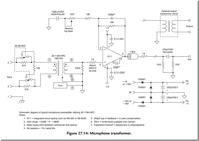
For more demanding studio applications, a more complex microphone preamplifier is demanded. First, the stage illustrated in Figure 27.13 is only suitable for unbalanced microphones, and the majority of high-quality microphones utilize balanced connection, as they are especially susceptible to hum pick-up if this type of circuit is not employed. Second, high-quality microphones are nearly always capacitor types and therefore require a polarizing voltage to be supplied for the plates and for powering the internal electronics. This supply (known as phantom power as mentioned earlier) is supplied via the microphone’s own signal leads and must therefore be isolated from the microphone preamplifier. This is one area where audio transformers (Figure 27.14) are still used, and an example of a microphone input stage using a transformer is illustrated, although plenty of practical examples exist where transformerless stages are used for reasons of cost.
Note that the phantom power is provided via resistors, which supply both phases on the primary side of the transformer, with the current return being via the cable screen. The
transformer itself provides some voltage gain at the expense of presenting a much higher output impedance to the following amplifier. However, the amplifier has an extremely high input impedance (especially so when negative feedback is applied) so this is really of no consequence. In Figure 27.14, amplifier gain is made variable so as to permit the use of a wide range of microphone sensitivities and applications. An ancillary circuit is also provided that enables the signal entering the circuit to be attenuated by 20 dB, which allows for very high output microphones without overloading the electronics.
Insert Points
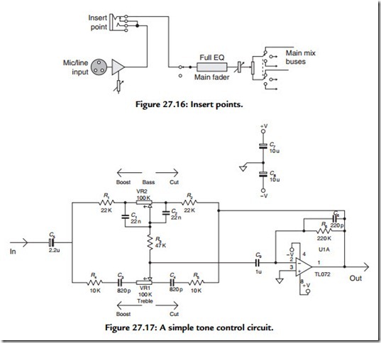
After the channel input amplifier, insert points are usually included. These allow external (outboard) equipment to be patched into the signal path. Note that this provision is usually via jack connectors, which are normalized when no plug is inserted (Figure 27.16).
Equalizers and Tone Controls
At the very least, a modern recording console provides a basic tone-control function on each channel input, like that shown in Figure 27.17. This circuit is a version of the classic circuit due to Baxandall. However, this type of circuit only provides a fairly crude
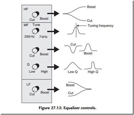
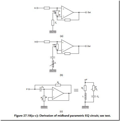
adjustment of bass and treble ranges, as illustrated in Figure 27.12. This type of response (for fairly obvious reasons) is often termed a “shelving” equalizer. So, the Baxandall shelving EQ is invariably appended with a midfrequency equalizer, which is tunable over a range of frequencies, thereby enabling the sound engineer to adjust the middle band of frequencies in relation to the whole spectrum (see also Figure 27.12). A signal manipulation of this sort requires a tuned circuit, which is combined within an amplifier stage, which may be adjusted over a very wide range of attenuation and gain (perhaps as much as ±20 dB). How such a circuit is derived is illustrated in Figure 27.18.
Imagine that Z1 is a small resistance. When the slider of VR1 is at position A, the input is heavily attenuated and the lower feedback limb of the op-amp is at its greatest value (i.e., the gain of the stage is low). Now imagine moving the slider of VR1 position B. The situation is reversed; the input is much less attenuated and the gain of the amplifier stage is high. This circuit therefore acts as a gain control because point A is arranged to be at the extreme anticlockwise position of the control. As a tone control this is obviously useless. However, in the second part of Figure 27.18(b), Z1 is replaced with a tunable circuit, formed by a variable inductor and a capacitor. This tuned circuit has high impedance—and therefore little effect—except at its resonant frequency, whereupon it acquires very low dynamic impedance. With the appropriate choice of inductor and capacitor values, the midfrequency equalizer can be made to operate over the central frequency range. The action of VR1 is to introduce a bell-shaped EQ response (as illustrated in Figure 27.12), which may be used to attenuate or enhance a particular range of frequencies, as determined by the setting of the variable inductor.
Inductor–Gyrators
As shown, the frequency adaptive component is designated as a variable inductor. Unfortunately, these components do not exist readily at audio frequencies and to construct components of this type expressly for audio frequency equalization would be very expensive. For this reason, the variable inductors in most commercial equalizers are formed by gyrators—circuits that emulate the behavior of inductive components by means of active circuits, which comprise resistors, capacitors, and op-amps. An inductor– gyrator circuit is illustrated in Figure 27.18(c). This is known as the “bootstrap” gyrator and its equivalent circuit is also included within the figure. Note that this type of gyrator circuit (and indeed most others) presents a reasonable approximation to an inductor that is grounded at one end. Floating inductor–gyrator circuits do exist but are rarely seen.
Operation of the bootstrap gyrator circuit can be difficult to visualize, but think about the two frequency extremes. At low frequencies, Ca will not pass any signal to the input of the op-amp. The impedance presented at point P will therefore be the output impedance of the op-amp (very low) in series with Rb, which is usually designed to be in the region of a few hundred ohms. Just like an inductor, the reactance is low at low frequencies. Now consider the high-frequency case. At HF, Ca will pass signal so that the input to the op-amp will be substantially that presented at point P. Because the op-amp is a follower, the output will be a low-impedance copy of its input. By this means, resistor Rb will thereby have little or no potential across it because the signal at both its ends is the same. Consequently, no signal current will pass through it. In engineering slang, the low-value resistor Rb is said to have been “bootstrapped” by the action of the op-amp and therefore appears to have a much higher resistance than it actually has. Once again, just like a real inductor, the value of reactance at high frequencies at point P is high. The inductor– gyrator circuit is made variable by the action of Ra, which is formed by a variable resistor component. This alters the breakpoint of the RC circuit Ca/Ra and thereby the value of the “virtual” inductor.
In recent years, the fascination in “retro” equipment has brought about a resurgence of interest in fixed inductor–capacitor type equalizers. Mostly outboard units, these are often passive EQ circuits [often of great complexity, as illustrated in Figure 27.18(d)], followed by a valve line amplifier to make up the signal gain lost in the EQ. In a classic LC-type equalizer, the variable-frequency selection is achieved with switched inductors and capacitors.
Often it is also useful to control the Q of the resonant circuit so that a very broad, or a very narrow, range of frequencies can be affected as appropriate. Hence the inclusion of the Q control as shown in Figure 27.12. This effect is often achieved by means of a series variable resistor in series with the inductor–capacitor (or gyrator–capacitor) frequency- determining circuit.
Effect Send and Return
The effect send control feeds a separate mix amplifier. The output of this submix circuit is made available to the user via an effect send output on the back of the mixer. An effect return path is also usually provided so that the submix (suitably “effected”—usually with digital reverberation) can be reinjected into the amplifier at line level directly into the main mix amplifiers.
Faders and Pan Controls
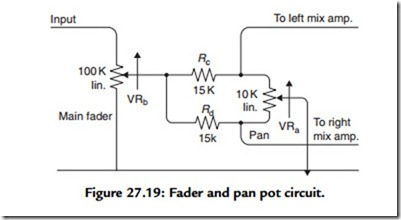
Beneath the effect send control is the pan control and the main fader. Each channel fader is used to control the contribution of each channel to the overall mix as described earlier. A design for a fader and pan pot is illustrated in Figure 27.19. The only disadvantage of the circuit is that it introduces loss. However, its use is confined to a part of the circuit where the signal is at a high level and the Johnson noise generated in the network is very low since all the resistances are low. The circuit takes as its starting point that a semilog audio-taper fader can be obtained using a linear potentiometer when its slider tap and “earthy” end is shunted with a resistor one-tenth of the value of the total potentiometer
resistance. Resistors Rc and Rd and VRa, the pan pot itself, form this one-tenth value network. Because the slider of the pan pot is grounded and the output signal is obtained from either end of the pan pot, it is clear that in either extreme position of VRa, all the signal will appear on one channel and none on the other. It is then only a matter of deciding whether the control law of the pan pot is of the correct type. The calculation of the control law obtained from the circuit is complicated because the signal level fed to left and right channels is not proportional to the resistive value of each part of VRa. This is because the total value of the network Rc, Rd, and VRa, although reasonably constant, is not the same irrespective of the setting of VRa and so the resistive attenuator comprising the top part of VRb and its lower part, shunted by the pan pot network, is not constant as VRa is adjusted. Furthermore, as VRa is varied, so the output resistance of the network changes and, since this network feeds a virtual-earth summing amplifier, this effect also has an influence on the signal fed to the output because the voltage-to-current converting resistor feeding the virtual-earth node changes value. The control law of the final circuit is nonlinear: the sum of left and right, when the source is positioned centrally, adding to more than the signal appearing in either channel when the source is positioned at an extreme pan position. This control law is very usable with a source seeming to retain equal prominence as it is “swept across” the stereo stage.
Mix Amplifiers
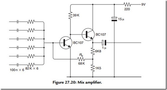
The mix amplifier is the core of the audio mixer. It is here that the various audio signals are combined together with as little interaction as possible. The adoption of the virtual- earth mixing amplifier is universal. An example of a practical stereo mix amplifier is shown in Figure 27.20. Here, the summing op-amp is based on a conventional transistor pair circuit. The only difficult decision in this area is the choice of the value for Rb. It is this value, combined with the input resistors, that determines the total contribution each input may make to the final output.
Line-Level Stages
Line-level audio stages are relatively straightforward. Signals are at a high level, so noise issues are rarely encountered. The significant design parameters are linearity, headroom, and stability. Another issue of some importance is signal balance, at least in professional line-level stages, which are always balanced. Of these, output-stage stability is the one most often ignored by novice designers.
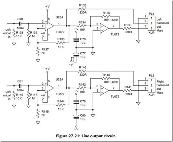
A high degree of linearity is achieved in modern line-level audio stages by utilizing high open-loop gain op-amps and very large feedback factors. The only issue remaining, once the choice of op-amp has been made, is available headroom. This is almost always determined by choice of power supply rails. Taking a typical audio op-amp (TL072, for example), maximum output swing is usually limited to within a few volts of either rail. So, furnished with 12-V positive and negative supplies, an op-amp could be expected to swing 18 Vpk-pk. This is equivalent to 6.3 V rms, or 16 dBV, easily adequate then for any circuit intended to operate at 0 VU = -10 dBV. In a professional line-output circuit, like that shown in Figure 27.21, this voltage swing is effectively doubled because the signal appears “across” the two opposite phases. The total swing is therefore 12.6 V rms, which is equivalent to 24 dBu. For equipment intended to operate at 0 VU = +4 dBu, such a circuit offers 20 dB headroom, which is adequate. However, ±12-V supplies really represent the lowest choice of rail volts for professional equipment and some designers prefer to use 15-V supplies for this very reason.
Looking again at the output stage circuit illustrated in Figure 27.21, note the inclusion of the small value resistors in the output circuit of the op-amps. These effectively add some real part to the impedance “seen” by the op-amp when it is required to drive a long run of audio cables. At audio frequencies, the equipment interconnection cable looks to the output stage as a straightforward—but relatively large—capacitance. Also, a large
negative reactance is, almost always, an excellent way to destabilize output circuits. Output “padding” resistors, such as R132 and R133, help a great deal in securing a stable performance into real loads.
Line-level input stages present different problems. Note that the function performed by the circuit in Figure 27.21, over and above its duty to drive the output cables, is to derive an equal and opposite signal so as to provide a balanced audio output from a single-ended, unbalanced input signal. This is a common feature of professional audio equipment because, although balanced signals are the norm outside the equipment, internally most signals are treated as single ended. The reasons for this are obvious;
without this simplification all the circuitry within, for example, a console would be twice as complex and twice as expensive.
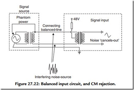
The line-level input stage on professional equipment therefore has to perform a complementary function to the output stage to derive a single-ended signal from the balanced signal presented to the equipment. Conceptually, the simplest circuit is a transformer, like that shown in Figure 27.22. In many ways this is an excellent solution for the following reasons: it provides electrical isolation, it has low noise and distortion, and it provides good headroom, provided the core doesn’t saturate. But, most important of all, it possesses excellent common- mode rejection (CMR). That means that any signal that is common (i.e., in phase) on both signal phases is rejected and does not get passed on to following equipment. By contriving the two signal conductors within the signal cable to occupy—as nearly as possible—the same place, by twisting them together, any possible interference signal is induced equally in both phases. Such a signal thereafter cancels in the transformer stage because a common signal cannot cause a current to flow in the primary circuit and cannot, therefore, cause one to flow in the secondary circuit. This is illustrated in Figure 27.22 as well.
Another advantage of a balanced signal interface is that the signal circuit does not include ground. It thereby confers immunity to ground-sourced noise signals. On a practical level it also means that different equipment chassis can be earthed, for safety reasons, without incurring the penalty of multiple signal return paths and the inevitable “hum loops” this creates. However, transformers are not suitable in many applications for a number of reasons. First, they are very expensive. Second, they are heavy, bulky, and tend to be microphonic (i.e., they have a propensity to transduce mechanical vibration into electrical energy!) so that electronically balanced input stages are widely employed instead. These aim to confer all the advantages of a transformer cheaply, quietly, and on a small scale. To some degree, an electronic stage can never offer the same degree of CMR, as well as the complete galvanic isolation, offered by a transformer.
