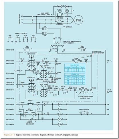
The schematics presented in this text so far have been small and intended to teach circuit logic and how basic control systems operate. Schematics in industry, however, are often much more complicated and may contain several pages. Notation is generally used to help the electrician interpret the meaning of certain components and find contacts that are controlled by coils. The schematic shown in Figure 25 – 1 is part of a typical industrial control schematic. Refer to this schematic to locate the following information provided about the control system.
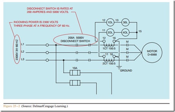
1. At the top left-hand side find the notation: (2300V 38 60 Hz). This indicates that the motor is connected to a 2300 volt, three-phase, 60 hertz power line (Figure 25 – 2).
2. To the right of the first notation, locate the notation: (200A 5000V DISCONNECT SWITCH). This indicates that there is a 200 ampere disconnect switch, rated at 5000 volts, that can be used to disconnect the motor from the power line. Also notice that there are six contacts for this switch, two in each line. This is common for high voltage disconnect switches.
3. At the top of the schematic, locate the two current transformers, 1CT and 2CT. These two current transformers are used to detect the amount of motor current. Current transformers produce an output current of 5 amperes under a short circuit condition. The notation beside each CT indicates that it has a ratio of 150 to 5. The secondary of 1CT is connected to 1OL and 3OL. The secondary of 2CT is connected to 2OL and 4OL. Overload coils 1OL and 3OL are connected in series, which forces each to have the same current flow. Also note that coil symbols (not heater symbols) are used for the overloads. This indicates that these overload relays are magnetic, rather than thermal.
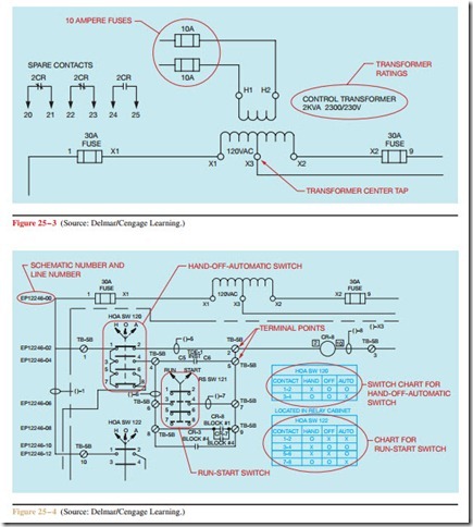
4. Locate the two 10 ampere fuses connected to the primary of the control transformer (Figure 25 – 3). The control transformer is rated at 2 kilovolt-amperes (2000 volt-amperes). The high voltage winding is rated at 2300 volts and the secondary winding is rated at 230 volts. Also note that the secondary winding contains a center tap (X3). The center tap can be used to provide 120 volts from either of the other X terminals. Terminals X1 and X2 are connected to 30 ampere fuses.
5. To the left of the 30 ampere fuse connected to terminal X1, locate the notation (EP12246-00) (Figure 25 – 4). This notation indicates that you are looking at Electrical Print 12246, and line 00. Most multi-page schematics will use some form of notation similar to this to indicate the page and line number you are viewing.
6. On line number EP12246-02, locate the HAND- OFF-AUTOMATIC switch labeled HOA SW 120. Also locate the contact chart for this switch just to the right of the center of the schematic. The chart indicates connection between specific terminals for different settings of the switch. The X indicates
connection between terminals and O indicates no connection. Notice that in the HAND position, there is connection between terminals 1 and 2. There is no connection between terminals 3 and 4. In the OFF position, there is no connection be- tween any of the terminals. In the AUTO position, there is connection between terminals 3 and 4 but no connection between terminals 1 and 2. Refer- ring back to the switch itself, notice that there are three arrows drawn at the top of the switch. One arrow points to H, one points to O, and one points to A. The line connected to the arrowhead pointed at H is shown as a solid line. The lines connected to the other two arrowheads are shown as broken or dashed. The solid line represents the position the switch is set in for the contact arrangement shown on the schematic. The schematic indicates that at the present time there is a connection between terminals 1 and 2, and no connection between terminals 3 and 4. This is consistent with the contact chart for this switch.
7. Locate the RUN-START switch (RS SW 121) to the right and below HOA SW 120. A contact chart is not shown for this switch. Since there are only two
positions for this switch, a different method is employed to indicate contact position for the different switch positions. Notice that arrowheads at the top of the switch are pointing at the RUN and START positions. The line drawn to the RUN position is solid and the line drawn to the START position is shown as broken or dashed. The schematic shows a solid line between switch terminals 1 and 2, and 5 and 6. Dashed lines are shown between terminals 3 and 4, and 7 and 8. When the switch is set in the RUN position, there is a connection between terminals 1 and 2, and 5 and 6. When the switch is in the START position, there is a connection between terminals 3 and 4, and 7 and 8.
8. On line 02, there are three terminals marked TB- 5B. These indicate terminal block points. Locate the terminal with 2 drawn beside it. This wire position is located on screw terminal #2 of terminal point 5B. Another terminal block point is shown below it. This terminal location is screw terminal #5 of terminal point 5B.
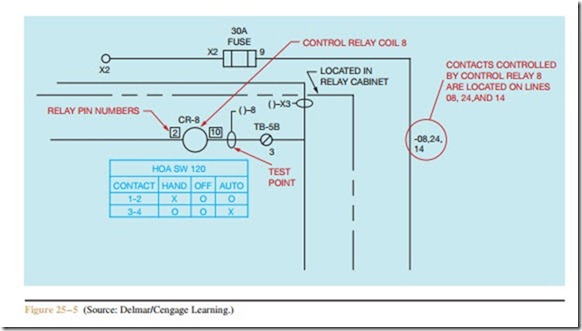
9. Find relay coil CR-8 on line 02 (Figure 25 – 5). CR stands for Control Relay. Notice that the numbers 2 and 10 on each side of the coil are shown inside a square box. The square box indicates that these are terminal numbers for the relay and should not be confused with wire numbers. Terminals 2 and 10 are standard coil connections for relays designed to fit into an eleven-pin tube socket. If you were trying to physically locate this relay, the pin numbers would be a strong hint as to what you are trying to find.
10. Beside pin number 10 of relay coil CR-8 is a circle with a line connected to it. The line goes to a symbol that looks like ()–8. This indicates a test point. Test points are often placed at strategic points to aid in troubleshooting when it becomes necessary.
11. At the far right-hand side of line 02 is the notation (-08, 24, 14). These numbers indicate the lines on the schematic where contacts controlled by relay coil CR-8 can be found. Find the contacts labeled CR-8 on these lines of the schematic.
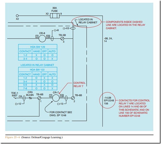
12. Locate coil CR-7 on line 14 (Figure 25 – 1 and Figure 25 – 6). At the far right-hand side, find the notation (-14, 08, EP12248 156). This notation again indicates the places where contacts controlled by coil CR-7 can be found. CR-7 contacts are located on lines 14 and 08 in this schematic and on line 156 of Electrical Print #12248.
13. At the right side of the schematic between lines 00 and 02 is the notation LOCATED IN RELAY CABINET. An arrow is pointing at a dashed line. This gives the physical location of such control components as starters, relays, and terminal blocks. Push buttons, HOA switches, pilot lights, and so on are generally located on a control terminal where an operator has access to them.
These are notations that are common to many industrial control schematics. Nothing is standard, however. Many manufacturers use their own numbering and notation system, specific to their company. Some use the NEMA symbols that are discussed in this text and others do not. With practice and an
understanding of basic control logic and schematics, most electricians can determine what these different symbols mean and the way they are used in a circuit. The old saying “Practice makes perfect” certainly ap- plies to reading schematic diagrams.
Review Questions
Refer to Figure 25 – 1 to answer the following questions.
1. When switch HOA SW 122 is in the OFF position, which contacts have connection between them?
2. How much voltage will be applied to coil 1CR when it is energized?
3. Referring to switch RS SW 123, in what position must the switch be set to make connection between terminals 3 and 4?
4. What are the terminal numbers for the two normally open spare contacts controlled by coil 2CR?
5. How much voltage is applied to coil CR-7 when it is energized?
6. What contact(s) is/are located between screw numbers 8 and 9 of terminal block 5B?
7. Between which terminal block and screw numbers is relay coil CR-7 located?
8. Assume that HOA SW 120 has been set in the AUTO position. List four ways by which coil CR-8 could be energized.
9. In what position must switch HOA SW 123 be set to make connection between terminals 3 and 4?
10. If one of the magnetic overload relays opens its contact, how can it be reset?
