RADIO HARDWARE
All radio communications systems consist of three basic pieces of hardware: transmitter, receiver, and antenna. In some systems, the transmitter and receiver are packaged and used separately, while in others they are combined into a single package and called a transceiver.
Transmitters
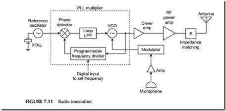
The radio signal is produced by the transmitter. A general block diagram that applies to virtually every transmitter is shown in Figure 7.11. The radio signal
is generated at a low power level by a frequency synthesizer. This uses a phase-locked loop (PLL) with a crystal (XTAL) oscillator reference. A variable-frequency divider is used to set the frequency of operation. The FCC is really fussy about the frequency at which transmitters work and, therefore, the frequency must be precisely set and extremely stable. A quartz crystal reference oscillator is normally used to achieve this objective.
The low-level signal produced by the voltage-controlled oscillator (VCO) is then amplified by one or more driver amplifiers to boost the power level. Next, the microphone signal is fed to the modulator. The modulator changes the fre- quency or phase of the RF signal in accordance with the voice, digital data, or other information to be transmitted. That signal is applied to the PLL VCO.
The modulated signal is sent to additional RF power amplifiers, usually referred to as drivers. Each succeeding stage boosts the signal power by a specific amount. A final RF power amplifier produces the desired amount of out- put power. From there, impedance (Z) matching circuits are used to match the high-power amplifier to the antenna for maximum power radiation.
The physical realization of the transmitter can vary all the way from a single integrated circuit chip the size of a postage stamp to something that can fill up a moderately large building. The size depends on the operating frequency and the amount of output power desired. Very-low-power, high-frequency radio transmitters for garage door openers and remote keyless entry systems on cars are fully self-contained within a single integrated circuit. High-power radio broadcast transmitters at low frequencies may fill a small room. The higher the power and the lower the frequency, the larger the transmitter.
Receivers
The job of the receiver is to translate the weak radio signal picked up by the antenna into an output that fully recovers the originally transmitted information.
By the time the radio signal reaches the receiving antenna, it is extremely weak and, therefore, the primary job of the receiver is to boost the signal level. Therefore, the receiver consists mainly of a series of amplifiers that increase the level of the small signal to a point where the original information can be recovered.
The amount of amplification provided by a receiver determines itssensitivity. Another job of the receiver is to provide selectivity so that the desired signal can be picked out of the thousands of signals being transmitted simultaneously by other transmitters. The receiver’s job is to select just the desired one and to reject all of the others. This is what we refer to as the selectivity of the receiver.
A third function of the receiver is to recover the original information. A circuit called a demodulator removes the voice, video, or digital data from the carrier. Finally, output amplifiers reproduce the signal as desired, such as a voice signal in a speaker.
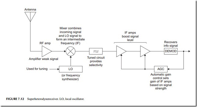
Figure 7.12 is a block diagram of a superheterodyne receiver. The incoming signal is usually amplified by an RF input amplifier often called a low-noise amplifier (LNA) and then fed to a circuit called amixer. The mixer is a frequency-translation circuit that converts the incoming signal, regardless of its frequency, along with its modulation to a lower intermediate frequency (IF). This allows the receiver to use a fixed-frequency amplifier system where most of the gain and selectivity of the receiver is achieved. The mixer takes the input signal and mixes it with a high-frequency sine wave signal generated internally in the receiver by what is called a local oscillator (LO). The LO is usually a frequency synthesizer. The result of the mixing is output signals that are the sum and difference frequencies of the input and oscillator signals. The IF amplifier is normally tuned to select only the difference frequency. Tuning is accomplished by changing the local oscillator frequency. The local oscillator in most channelized receivers is some type of PLL frequency synthesizer.
The IF amplifier boosts the signal level considerably. Its selectivity ensures that signals whose frequencies are above or below the desired signal are effectively eliminated. The IF amplifier also has a built-in feedback control circuit that automatically adjusts its gain to the level of the incoming signal. This feature is called automatic gain control (AGC). AGC permits the receiver to pick up both strong local signals and very weak distant signals. When very strong signals are received, the AGC automatically reduces the gain of the IF amplifier to minimize circuit overload and signal distortion. When very weak signals are received, the AGC adjusts the gain of the IF amplifier for higher amplification.
The demodulator circuit, sometimes called the detector, follows the IF amplifier. It removes the carrier and recovers the desired information signal. From there, additional processing takes place to either boost the signal level or to shape it before it appears at the output.
Most receivers that we are familiar with have a speaker as the primary out- put. But there are exceptions, such as the picture tube in a TV set or the motor in a garage door opener. The receiver may also put out digital data that goes straight to a computer.
Most communications systems use both a transmitter and a receiver. In two- way radio, both send and receive capability is needed at both ends of the communications channel. Therefore, the receiver and transmitter are packaged together in the same housing to create a transceiver. Small portable transceivers are called hand-helds, walkie-talkies, or cellular telephones.
The transmitters and receivers are typically the same as those described earlier. However, in some cases, the transmitter and receiver may share circuits. They virtually always share the antenna and a common power supply like a battery. In some cases, a single-frequency synthesizer may generate both the receiver LO signal as well as the transmitter carrier.
ISM Band Transceiver
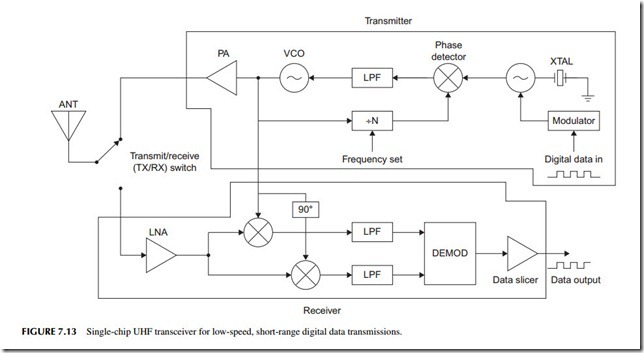
The ISM band refers to specific frequencies set aside for wireless industrial, scientific, and medical (ISM) applications. The most common frequencies in the United States are 315, 433, and 915 MHz. The frequency 868 MHz is widely used in Europe. These unlicensed frequencies are used for simple monitor and control applications using low-speed digital data over short ranges. Some common examples are garage door openers, remote keyless entry on cars, remote thermometers, tire pressure gauges, security and fire alarms, home automation, and any telemetry or remote control application. The radios used for this are typically single ICs to which an antenna, a battery, a housing, and the input data are added. The devices are available as a receiver, a transmitter, or a complete transceiver. Figure 7.13 is a block diagram of a typical transceiver.
The transmitter section uses an external crystal to serve as the reference to an internal PLL frequency synthesizer to set the frequency. The PLL actually multiplies the crystal frequency by some N value to get the desired output. If the crystal frequency is 6.77 MHz and the divide ratio is 64, the output would be 433.28 MHz. The serial digital data input coming from a sensor, an analog-to-digital converter (ADC), or a computer frequency modulates the crystal oscillator to create the FSK signal. A power amplifier (PA) after the transmit VCO boosts the power up into the 1- to 100-milliwatt range. The output goes to the antenna. A transmit/receive switch allows the antenna to be shared in a half-duplex system.
The receiver is a special version of a superheterodyne. The input signal from the antenna is boosted in amplitude by the LNA and applied to the mixers. The local oscillator is set to the incoming signal frequency (also the transmit frequency), so the mixers generate a difference of zero. This is called direct conversion or zero IF. Two mixers are used and the local oscillator is shifted 90 degrees in phase between the two. This gives two zero IF outputs that are filtered. Zero IF does not mean a nonexistent output signal. It just means that the FSK signal is recovered directly at its data rate. The I and Q signals are 90 degrees out
of phase and this allows the digital data to be more easily demodulated. A data slicer, a circuit like a comparator, is used to shape the signal into a clean binary bit stream. With this kind of radio, the range is limited. It may be only a few feet or up to a mile or so depending on the antenna, environment, or application.


