After studying this unit, the student will be able to:
• Describe the difference between closed and open push buttons
• Draw the wiring diagram symbols for push buttons and pilot lights
• Draw simple circuits using normally open and closed push buttons
• Connect combination push buttons in simple circuits
• Explain single and double break contacts
• List type of control operators on control stations
• Draw simple circuits using a selector switch
• Wire simple circuits with a selector switch
PUSH BUTTONS
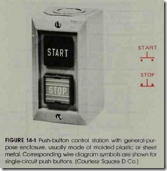
A push-button station is a device that pro vides control of a motor through a motor starter by pressing a button which opens or closes con tacts. It is possible to control a motor from as many places as there are stations-through the same magnetic controller. This can be done by us ing more than one push-button station. A single circuit push-button station is shown in figure 14-1.
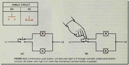
Two sets of momentary contacts are usually provided with push buttons so that when the but ton is pressed, one set of contacts is opened and the other set is closed. The use of this combina tion push button is simply illustrated in the wiring diagram of figure 14-2. When the push button is in its normal position as shown in figure 14-2(A), current flows from L1 through the normally closed contacts, through the red pilot light (on top) to L2 to form a complete circuit; this lights FIGURE 14-1 Push-button control station with general-pur pose enclosure. usually made of molded plastic or sheet metal. Corresponding wire diagram symbols are shown for single-circuit push buttons. (Courtesy SquareD Co.)
the lamp. Since the lower push-button circuit is opened by the normally open contact, the green pilot lamp does not glow. Note that this situation is reversed when the button is pushed, see figure 14-2(B). Current now flows from L1 through the pushed closed contact and lights the green pilot lamp when completing the circuit to L2. The red lamp is now out of the circuit and does not glow. However , because the push buttons are momen tary contact (spring loaded), we return to the po sition shown in figure 14-2(A) when pressure on the button is released. Thus, by connecting to the proper set of contacts, either a normally open or a normally closed situation is obtained. Normally open and normally closed mean that the contacts are in a rest position, held there by spring tension, and are not subject to either mechanical or electri cal external forces. (See the Glossary for more de tailed definitions. )
Push-button stations are made for two types of service: standard duty stations for normal appli cations safely passing coil currents of motor start ers up to size 4, and heavy duty stations, when the push buttons are to be used frequently .and sub jected to hard or rough usage. Heavy duty push button stations have high contact ratings.
The push-button station enclosure containing the contacts is usually made of molded plastic or sheet metal. Some double-break contacts are made of copper. However, in most push buttons, silver to-silver contact surfaces are provided for better electrical conductivity and longer life.
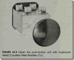
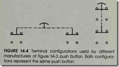
Figure 14-3 shows a combination, normally open and normally closed, push-button unit with a mushroom head for fast and easy access such as may be required in a safety circuit. This is also called a palm-operated push button, especially when it is used as a safety device for both operator and machine, such as a punch-press or emergency stop in a control station. The push-button terminals in figure 14-2 represent one-half of the terminals shown in figures 14-3 and 14-4, for a double-pole, double-throw push button.
Since control push buttons are subject to high momentary voltages caused by the inductive effect of the coils to which they are connected, good clearance between the contacts and insulation to ground and operator is provided.
The push-button station may be mounted adjacent to the controller or at a distance from it. The amount of current broken by a push button is usually small. As a result, operation of the controller is hardly affected by the length of the wires leading from the controller to a remote push-but ton station.
Push buttons can be used to control any or all of the many operating conditions of a motor, such as start, stop, forward, reverse, fast, and slow. Push buttons also may be used as remote stop but tons with manual controllers equipped with poten tial trip or low-voltage protection.
SELECTOR SWITCHES
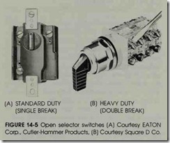
Selector switches, as can be seen in figure 14-5, are usually “maintained” contact positions, with three and sometimes two selector positions. Selector switch positions are made by turning the operator knob-not pushing it. Figure 14-S(A) is a single-break contact arrangement, and figure 14-S(B) is a double-break contact, disconnecting the control circuit at two points. These switches may also have a spring return to give momentary contact operation.
Figure 14-6A shows a single break contact se lector switch connected to two lights. The red light may be selected to glow by turning the switch to the red position. Current now flows from line 1 through the selected red position of the switch, through the red lamp to line 2, completing the cir cuit. Note this switch has an off position in the center. In figure 14-6(B), there are two position
selector switches available, with no off position. Here, whichever light is selected would burn con tinuously.
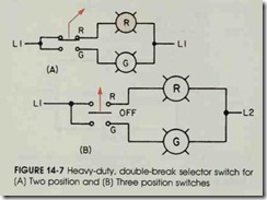
Figure 14-7(A) is an elementary diagram of the heavy duty, double-break selector switch sim ilarly shown in figure 14-5. Note that the red light will glow (see A) with the two-position switch in this position, the green indicating lamp is de-en ergized, and there is no “off’ position. Figure 14-7(B) illustrates a three-position selector switch containing an “off’ position. Both lamps may be turned off using this switch, but not in (A).
CONTROL STATIONS
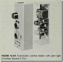
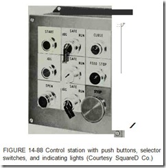
A control station may contain push buttons alone, figure 14-8A, or a combination of push but tons, selector switches and pilot lights (indicating lights), figure 14-8B. Indicating lights may be mounted in the enclosure. These lights are usually red or green and are used for communication and safety purposes. Other common colors available are amber, blue, white, and clear. They indicate when the line is energized, the motor is “running, or any other condition is designated.
Control stations may also include switches that are key, coin, or hand operated wobble sticks. A wobble stick is a stem-operated push button, for operation from any direction. There are ball lever push button operators for a gloved hand or for fre quent operations.
Name plates are installed to designate each control operation. These can be seen in figures 14-1 and 14-8. These control operators are com monly used in control circuits of magnetic devices in factory production machinery.Combination indicating light, nameplate, push button units are available. These illuminated push buttons and indicating lights are designed to save space in a wide variety of applications such as control and instrument panels, laboratory instru ments, and computers. Miniature buttons are also used for this purpose.
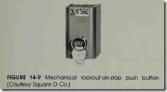
Standard control station enclosures are avail able for normal general-purpose conditions, while special enclosures are used in situations requiring watertight, dust-tight, oiltight, explosion-proof, or submersible protection. Provisions are often made for padlocking stop buttons in the open position (for safety purposes), figure 14-9. Relays, contac tors and starters cannot be energized while an electrician is working on them with the stop but ton in this position.
The Push-Pull Operator
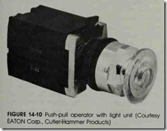
Another type of push-button control is the push-pull operator. This control contains two sets of contacts in one unit. One set of contacts is op erated by pulling outward on the button and the other set is operated by pushing the button. The head of the push-pull operator is made in such a manner as to permit a machine operator to pull outward on the button by placing two fingers be hind it. Figure 14-10 shows a push-pull operator control. The head of the control can be pushed to operate the other set of contacts.
There are two types of push-pull operators. The type used is determined by the requirements of the circuit. One type of control contains two normally open momentary contacts. Figure 14-11 shows a schematic drawing of this control. In its normal position, neither movable contact A or B connects with either of the stationary contacts. In figure 14-12, the control has been pulled outward. This causes movable contact A to connect with two of the stationary contacts. Movable contact B does not connect with its stationary contacts.
If the push-pull operator is pressed, movable contact B connects with a set of stationary contacts as shown in figure 14-13. Movable contact A does not connect with its stationary contacts.
The Push-Pull Operator
Another type of push-button control is the push-pull operator. This control contains two sets
This type of push-pull operator control can be used with run-jog controls. An example of this type of control is shown in Unit 41.
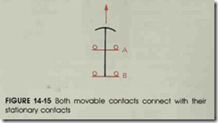
The second type of push-pull operator has one normally open contact and one normally closed contact. Figure 14-14 shows a schematic drawing of this type of control. When this type of push-pull operator is in its normal position, mov able contact A is open and movable contact B is closed.
When the button is pulled outward, contact A connects with its stationary contacts, and con tact B maintains connection with its stationary contacts. Figure 14-15 illustrates this condition. When the button is released, the movable contacts return to their normal position.
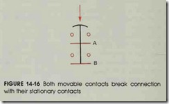
When the push button is pressed, contact B breaks the connection with its stationary contact. Figure 14-16 shows this condition.
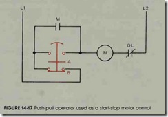
This type of push-pull operator control can be used as a start-stop motor control station. The advantage of this type of control is that it requires the space of only one push-button control element instead of two. Also, since the control must be pulled outward to start the motor and pressed in ward to stop the motor, the possibility of acci dently pushing the wrong button is eliminated.
A start-stop control circuit using the push pull operator is shown in figure 14-17. When the push-pull operator is pulled outward, contact A completes a circuit to motor starter coil M. Nor mally open contact M, connected parallel to con tact A, closes to maintain the circuit to coil M when the button is released. When the push-pull operator is pressed, movable contact B breaks the circuit to motor starter coil M and the circuit de energizes.
REVIEW QUESTIONS
1. What is meant by normally open contacts and normally closed contacts?
2. Why is it that normally open and normally closed contacts cannot be closed simultaneously?
3. How are colored pilot lights indicated in wiring diagrams?
Select the best answer for each of the following.
4. A single-break control is a
a. heavy duty selector switch
b. single-circuit push button
c. standard duty selector switch
d. double-circuit push button
5. Control stations may contain
a. push buttons
b. selector switches
c. indicating lights
d. all of these
6. A wobble stick is
a. operated from any direction
b. knob controlled
c. palm controlled
d. glove operated
7. Common selector switches are
a. one position
b. two positions
c. three positions
d. two and three positions
8. Most push buttons are
a. momentary contact
b. single contact
c. double contact
d. a combination
9. Control station enclosures are
a. general purpose
b. explosion proof
c. watertight
d. all of these
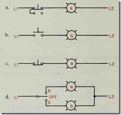
10. The diagram that illustrates a single circuit, normally closed push button is
11. Another type of push-pull operator contains
a. Two momentary normally closed contacts
b. One maintained normally open contact and one momentary normally closed contact
c. Two maintained normally open contacts
d. One maintained normally closed contact and one momentary normally open contact
12. Another type of push-pull operator contains
a. Two momentary normally closed contacts
b. One maintained normally open contact and one momentary normally closed contact
c. Two maintained normally open contacts
d. One maintained normally closed contact and one momentary normally open contact
