Stromberg Carburetors
ONE & TWO BARREL CARBS
WA & WW Series
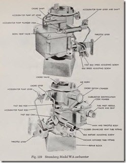
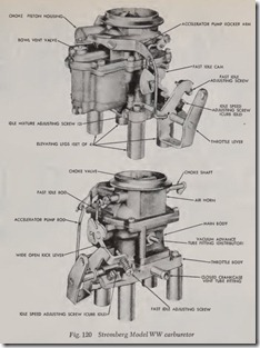
These carburetors are fundamentally the same, the WA model being a one barrel unit whereas the WW Model is a two barrel carburetor, Figs. 119 and 120. Both models consist of two main assem blies, namely the air horn and the main body. The air hom serves as a fuel bowl cover and includes parts of the idle system, choke system, accelerat ing and power systems. The main body includes the fuel inlet, fuel bowl, fuel metering systems and throttle mechanism.
Float System
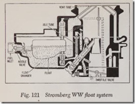
Fig. 121. Fuel enters the carburetor at the gaso line inlet, flowing through the float needle valve and seat and into the float chamber, where it is maintained at a constant level by the float.
The float chamber can be vent ed by either an extemf!l or an internal vent. The internal vent is in the air horn and, because of its position, the air pressure on the gasoline in the float chamber is balanced with the pressure in the air horn. This results in the mixture remaining correct, regard less of the fact that dirt gradually accumulates in the air cleaner.
Idle System (1st Stage)
Fig. 121. When an engine idles at its slowest speed, the throttle is held open slightly by the throttle stop screw. The idle speed may be varied by turning this screw. Any throttle valve position thus obtained controls the amount of air entering the engine and thereby regulates the engine’s idling speed.
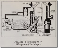
At closed throttle or slow engine speeds, the fuel is delivered through the idle system. The fuel is taken from the base of the main discharge jet, flowing into the bottom of the idle tube, where it is metered. From the idle tube it flows through a connecting channel where air from the idle air bleed is mixed with it so that a mixture of fuel and air passes down the channel and is discharged from the idle discharge holes. The idle needle valve controls the quantity of fuel discharged from the primary hole, thereby controlling the mixture ratio.
Idle System (2nd Stage)
Fig. 122. When the engine runs at no load, slightly faster than idle speed, it operates in the second stage of the idle system . While in this range of operation the fuel is delivered into the barrel from the upper discharge hole as well as from the needle valve hole.
Main Metering System
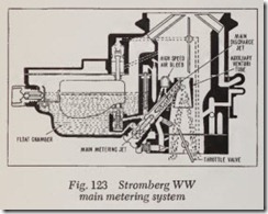
Fig. 123. The main metering system controls the flow of fuel during part throttle operation. Fuel flows from the float chamber into the main meter ing jet and then into the base of the main dis charge jet. Air is bled through the high speed bleed into the main discharge j et so that a mixture of fuel and air is disch arged from the main dis charge jet into the carburetor barrel.
The main discharge j et is designed so that if any vapor bubbles are formed in the hot gasoline, the vapors follow the outside channel around the main discharge jet instead of passing through the center of the jet. These vapor bubbles collect and condense in the dome-shaped high speed bleed, and thereby eliminate percolating troubles.
Power System
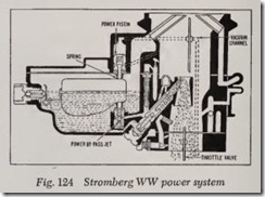
Fig. 124. For <t maximum power or high speed operation, a richer mixture is required than that necessary for lesser throttle opening.
A vacuum controlled piston automatically oper ates the power jet in accordance with the throttle opening. When the throttle is closed, a high mani fold vacuum is present and the power piston is moved to its “up” position against the tension of the spring. When the throttle is opened to a point where additional fuel is required, the manifold vacuum has decreased sufficiently so that the spring on the power piston moves the piston down, thereby opening the power jet to feed addi tional fuel into the main metering system.
Accelerating Pump System
Fig. 125. In most designs th e accelerating pump is directly connected to th e thr ottle so that when th e throttl e is closed, th e pu mp piston moves up, takin g in a supply of f uel from the float chamber through th e inlet check valve in the pump cyl inder.
When the throttle is opened suddenly, the pis ton on its down stroke creates a pressure that closes the inlet check valve, forcing open the by pass jet , and discharging a met ered quantity of fuel through the pump dischar ge nozzle. The pump duration spring provides a follow-up action so that th e discharge carries over a period of time.
